
- Shaft
- Molds&Tools
- Hydraulics And Pump
- Hair transplant needle
- Hydraulics And Pump
- Precision CNC Shaft Machining Manufacturer for High Performance Applications
- Energy Industry CNC Machining Parts Supplier
- Aerospace Structural Components for OEM Programs
- Aerospace Structural Components for OEM Programs
- Automotive & EV CNC Machining Parts Supplier for OEM and Tier 1
- Medical Device CNC Machining Services
DFM for Long Shaft CNC Turning: Reducing Risk Before Production

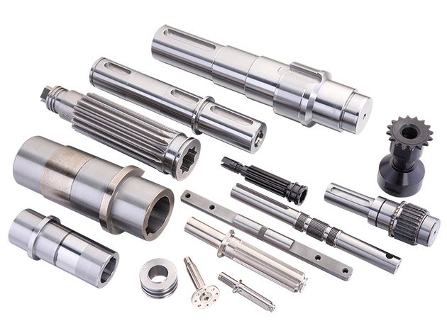
Long shaft components introduce deflection, chatter and concentricity risks that short turned parts do not face. Small design choices—material grade, diameter transitions, tolerance placement—determine whether a shaft can be machined repeatably at scale or becomes a high-scrap, high-touch project. Applying DFM for long shaft CNC turning early in the design cycle reduces tooling costs, stabilizes inspection outcomes and shortens the path from prototype to production.
Key answer: DFM for long shaft CNC turning addresses deflection, concentricity and fixturing constraints by controlling length-to-diameter ratio, specifying tolerances only where function requires them, selecting materials with predictable machinability, and designing features accessible to standard tooling. Early collaboration with the manufacturer on workholding and inspection strategy prevents rework and accelerates scale-up.
Why Long Shafts Demand Earlier DFM Collaboration
Shafts with length-to-diameter (L/D) ratios above 10:1 behave differently under cutting forces. Deflection increases with the cube of unsupported length, making dimensional control and high concentricity difficult without tailstock support, steady rests or specialized fixturing. A design that ignores these constraints may quote quickly but deliver inconsistent results once production begins.
Common manufacturability risks in long shaft turning include:
- Deflection under cutting load: Thin sections bend away from the tool, creating taper or out-of-round profiles.
- Chatter and surface finish variation: Unsupported length amplifies vibration, especially in interrupted cuts or hard materials.
- Concentricity drift: Multiple setups or inadequate support introduce runout between features.
- Inspection difficulty: Long shafts require specialized metrology; tight tolerances on inaccessible features increase measurement time and uncertainty.
These issues are not always visible in prototype quantities. They emerge during scale-up when batch-to-batch consistency matters and inspection becomes a bottleneck.
Material Selection and Its Impact on Turning Stability
Material choice affects deflection, tool life and thermal stability during long shaft machining. A stiffer material reduces deflection for a given L/D ratio, but harder grades increase cutting forces and heat, which can worsen dimensional drift if not managed.
Aluminum alloys such as 6061-T6 and 7075-T6 machine quickly with minimal deflection, but thermal expansion during continuous turning can shift dimensions if coolant strategy is inconsistent. Steel grades like 1045 and 4140 offer better rigidity but require slower feeds and sharper tooling to avoid work hardening on the surface. Stainless steels (303, 316) generate more heat and require chip-breaking tool geometries to prevent long stringy chips that interfere with surface finish.
For shafts requiring post-machining heat treatment, such as case hardening or induction hardening, dimensional stability after treatment must be considered. Specifying grinding stock and designing grinding-accessible features prevents costly rework when hardened surfaces fall outside tolerance.
Design Recommendations by Material Class
| Material Class | L/D Guideline | Key DFM Consideration |
|---|---|---|
| Aluminum (6061, 7075) | Up to 15:1 without steady rest | Thermal expansion; consistent coolant flow |
| Carbon Steel (1045, 4140) | Up to 12:1 without support | Tool deflection; chip control in deep cuts |
| Stainless (303, 316) | Up to 10:1 without support | Work hardening; chip evacuation |
| Titanium (Ti-6Al-4V) | Up to 8:1 without support | Low thermal conductivity; specialized tooling |
Tolerance Placement and Concentricity Control
Specifying tight tolerances across the entire shaft length increases setup time, tooling cost and inspection complexity. A more effective approach applies precision only where mating surfaces, bearing journals or functional diameters require it, and relaxes tolerances elsewhere.
Concentricity and total indicated runout (TIR) are particularly sensitive to fixturing method. A shaft turned in a single setup between centers will hold better concentricity than one requiring multiple chuck changes. When multiple diameters or features must hold tight runout relative to a datum, cross-drilled or perpendicular features should be machined in the same operation to avoid compounding positional error.
According to Premsa Industries, reducing the number of setups is one of the most effective ways to lower CNC machining cost and improve repeatability. Designing with single-setup machining in mind—by grouping tight-tolerance features within one clamping zone—directly supports this principle.
Practical Tolerance Guidelines
- Apply ±0.01 mm or tighter tolerances only to bearing seats, spline engagement zones and mating diameters.
- Use ±0.05 mm or ISO 2768-m for non-functional diameters and shaft body sections.
- Specify concentricity or runout only when assembly performance depends on it; typical achievable TIR is 0.01–0.02 mm for supported turning.
- Avoid specifying flatness or perpendicularity on turned faces unless they serve as datum surfaces; face turning naturally produces slight convexity.

Workholding and Fixturing Strategy
Long shaft turning requires either tailstock support, steady rests or both. Each method introduces setup time and positional constraints that should inform feature placement during design.
Tailstock support is effective for solid shafts with center-drilled ends, but limits access to the tailstock end during machining. Features requiring turning, threading or grooving near the tailstock end may require a second operation or a flip setup, increasing cycle time and introducing potential runout.
Steady rests support the shaft at one or more intermediate points, allowing access to both ends but requiring a smooth, consistent diameter at the contact zone. If the design includes an undercut, groove or diameter change at the steady rest location, the machinist must add a preparatory turning pass or use soft jaws, both of which add cost.
Designing shafts with a consistent diameter section near the midpoint—free of threads, grooves or tight-tolerance features—provides a stable steady rest zone and simplifies fixturing across production batches.
DFM Checklist for Long Shaft CNC Turning
- Confirm L/D ratio is compatible with material stiffness and available fixturing.
- Specify tolerances selectively: tight on functional features, relaxed elsewhere.
- Group tight-tolerance features within a single clamping or setup zone.
- Provide a smooth, uninterrupted diameter section for steady rest contact if L/D exceeds 10:1.
- Avoid tight concentricity or runout specifications across multiple setups unless inspection method is defined.
- Design threads, keyways and cross-holes accessible to standard tooling without custom fixtures.
- Include chamfers or radii at diameter transitions to reduce stress concentration and simplify tool pathing.
- Confirm post-machining processes (heat treatment, plating, grinding) are compatible with as-turned dimensions and tolerance stack-up.
- Share CAD early with the manufacturer to validate fixturing strategy and inspection feasibility before committing to production tooling.
When to Involve the Manufacturer in Design Review
Early collaboration reduces the risk of discovering manufacturability issues during quoting or first article inspection. A design review should occur before finalizing tolerances, selecting material or issuing a purchase order, especially when:
- L/D ratio exceeds 12:1 or shaft length exceeds 500 mm.
- Concentricity or runout tolerances are tighter than 0.02 mm.
- The shaft includes interrupted features (keyways, flats, cross-holes) that affect dynamic balance or fixturing.
- Post-machining heat treatment or surface hardening is required.
- Production volume justifies dedicated fixturing or tailored inspection protocols.
Integrated manufacturing systems that link CAD, process planning and inspection data can flag potential issues earlier and provide more reliable cost and lead time estimates than fragmented workflows.

Frequently Asked Questions
What length-to-diameter ratio requires special fixturing in CNC turning?
Shafts with L/D ratios above 10:1 typically require tailstock support or steady rests to control deflection and maintain concentricity. Below 10:1, standard chuck clamping is often sufficient, depending on material stiffness and tolerance requirements. Always confirm fixturing strategy with the manufacturer when L/D exceeds 8:1 and tolerances are tighter than ±0.02 mm.
How does material choice affect long shaft turning cost?
Softer, more machinable materials like aluminum and free-machining steel reduce cycle time and tool wear, lowering per-part cost. Harder materials such as stainless steel and titanium increase cutting forces, require slower feeds and may demand carbide or coated tooling, raising both machining time and tooling expense. Material-driven deflection also affects achievable tolerance, sometimes requiring additional operations or grinding.
Can tight concentricity be held across multiple setups?
Maintaining concentricity tighter than 0.02 mm across multiple setups is challenging without precision fixturing and datum transfer methods. Single-setup machining between centers or with synchronized steady rests offers the best concentricity control. If multiple setups are unavoidable, design features so critical concentricity requirements fall within one setup zone.
What is the most common DFM mistake in long shaft design?
Specifying uniform tight tolerances across the entire shaft length. This increases inspection time, setup complexity and scrap risk without improving function. A better approach applies precision selectively to bearing journals, spline zones and mating diameters, and relaxes tolerances on non-functional sections. This reduces cost while preserving performance.
How do cross-drilled holes affect turning fixturing?
Cross-drilled holes or radial features interrupt the continuous diameter needed for steady rest support. If holes must be present, position them outside the steady rest contact zone or plan for a secondary operation after turning. Cross-drilled turned parts also require careful tolerance specification, as positional accuracy depends on fixturing repeatability and tool access.
When should I request a manufacturability review?
Request a review before releasing drawings for tooling if the shaft has an L/D ratio above 10:1, concentricity requirements tighter than 0.02 mm, or post-machining processes like heat treatment or hard turning. Early feedback from the manufacturer can identify fixturing constraints, tolerance conflicts and inspection limitations that are difficult or costly to address after production begins. Submitting drawings early accelerates this process.
Conclusion
Effective DFM for long shaft CNC turning starts with understanding how length, diameter, material and tolerance interact with fixturing and inspection methods. Designing shafts that minimize setup changes, provide stable workholding zones and apply precision only where function demands it reduces cost, scrap and lead time while improving batch consistency. Engaging the manufacturer during design—not after quoting—ensures that fixturing, tooling and inspection strategies are feasible and aligned with production scale.
Sources
- Focused On Machining – 6 DFM Tips for CNC Turned Parts – focusedonmachining.com
- Premsa Industries – CNC Design Guide: DFM Rules for Better Parts, Lower Cost, and Faster Quotes – premsaindustries.com
- Protolabs – DFM Guidelines for CNC Machining – protolabs.com