
- Shaft
- Molds&Tools
- Hydraulics And Pump
- Hair transplant needle
- Hydraulics And Pump
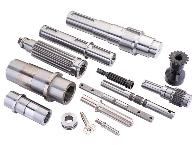
- Precision CNC Shaft Machining Manufacturer for High Performance Applications
- Energy Industry CNC Machining Parts Supplier
- Aerospace Structural Components for OEM Programs
- Aerospace Structural Components for OEM Programs
- Automotive & EV CNC Machining Parts Supplier for OEM and Tier 1
- Medical Device CNC Machining Services
CNC Machining Aircraft Structural Components Tolerances: A Practical Design and Inspection Guide

Key answer: CNC machining aircraft structural components tolerances depend on material hardness, part geometry, cutting dynamics, and fixture rigidity. Titanium and Inconel require lower feedrates and specialized tooling; 5-axis machines enable tighter control of complex geometries. Inspection at critical datums validates achievable tolerances before production.
Aircraft structural components demand uncompromising precision. A wing skin rivet hole 0.002″ out of tolerance can cause fastener misalignment, stress concentration, and potential fatigue failure. CNC machining aircraft structural components tolerances is not a simple specification—it is an engineering problem solved through material selection, process control, and real-time inspection feedback.
This guide explains how geometry, material, process, and inspection interact to determine what tolerances you can actually achieve in production, and what trade-offs matter to your sourcing decisions.
Why Aircraft Structural Tolerance Demands Differ from Standard CNC Work
Commercial machining often tolerates ±0.005″ or ±0.010″ easily. Aerospace structural work demands ±0.002″ to ±0.0005″ on critical features. The difference is not just precision—it is consequence.
Aircraft structures experience cyclic loading, thermal stress, and corrosive environments over 20,000+ flight hours. A tolerance stack that works in a single assembly may create stress risers in service. OEMs specify tight tolerances on datum surfaces, fit-critical holes, and load-bearing surfaces to ensure:
- Proper fastener preload and clamping force.
- Consistent fit with adjoining components.
- Predictable stress distribution under flight loads.
- Reduced rework and field failures.
When you source aircraft structural parts, your supplier must deliver not just accuracy, but repeatability—the same tolerance performance part after part, batch after batch.
How Material Choice Affects Achievable Tolerances
Titanium and Inconel dominate aerospace structures because they survive extreme temperature and fatigue. They also make tolerance control harder.
Titanium (Ti-6Al-4V) is difficult to machine because it:
- Exhibits low thermal conductivity—heat concentrates at the tool edge, causing rapid wear.
- Creates long, stringy chips that re-weld to the part surface if not controlled, raising surface roughness.
- Requires lower feedrates (0.002″–0.005″ per tooth) than aluminum, reducing productivity but improving surface finish and dimensional stability.
- Demands aggressive coolant flow to prevent thermal distortion during and after cutting.
Inconel (IN-718) is even more demanding:
- Work-hardens aggressively during cutting, blunting tools faster than titanium.
- Requires carbide or ceramic tooling, increasing tool cost and setup complexity.
- Feedrates drop to 0.001″–0.003″ per tooth, making cycle time the primary cost driver.
- Thermal growth during machining can cause dimensional drift if not compensated by in-process measurement.
For both materials, realistic tolerances in production are ±0.002″ to ±0.003″ on most features. Tighter tolerances (±0.0005″ to ±0.001″) are achievable but require premium tooling, slow feeds, and 100% in-process inspection. Budget accordingly when specifying tolerances below ±0.001″.
Process Variables That Control Tolerance Capability
A CNC machine’s rated accuracy is only the starting point. Real-world tolerance performance depends on how well the supplier controls these factors:
Fixture Rigidity and Repeatability
Part deflection is the silent tolerance killer. A thin-wall aircraft skin or a long cantilever beam will move under cutting force, then spring back. If the part springs back inconsistently, you get tolerance scatter. Aerospace suppliers use precision vises, custom tombstones, and preload optimization to hold parts rock-solid. Repeatability of fixture setup—within 0.0005″—is non-negotiable.
Tool Wear Compensation
Tool edge wear happens continuously. A dull tool pushes harder, generating heat and dimensional drift. Leading suppliers monitor tool wear in real time and adjust offsets every 2–10 minutes on critical features. This requires CNC programs with built-in measurement routines and operator discipline to log offsets accurately.
Thermal Management
Cutting generates intense localized heat. Titanium and Inconel parts expand as they warm, shifting dimensions by 0.0005″–0.001″ during a long cut. Coolant flow, machine warm-up cycles, and strategic rest periods between cuts all affect thermal stability. For critical tolerances, parts are allowed to cool to room temperature before final inspection.
5-Axis Orientation and Datum Control
Traditional 3-axis machines must reposition parts for each face, introducing setup error. 5-axis CNC machines keep parts stationary while the spindle rotates, enabling simultaneous control of multiple surfaces from a single datum. This reduces tolerance stack and improves geometric accuracy—especially for complex fuselage skins and wing ribs.

Inspection Strategy Validates and Locks Tolerances
A tolerance is only meaningful if you can measure it. Aircraft suppliers use three-tier inspection:
In-Process Measurement (IPM)
CMM probes or laser gauges measure critical features while parts are still in the fixture. If a dimension drifts out of spec, the operator corrects the offset before the next part runs. IPM catches thermal drift and tool wear before scrap is produced. It adds 5–15 minutes per part but is essential for tolerances tighter than ±0.002″.
First-Article Inspection (FAI)
Before production release, the first part is measured on a coordinate measuring machine (CMM) against the full drawing. All geometric tolerances—perpendicularity, runout, position, profile—are verified. FAI documents baseline capability and becomes the baseline for ongoing inspections.
Ongoing Batch Sampling
After FAI, every 10th to 25th part is pulled and measured on a CMM to confirm the process remains in control. Statistical control charts track trends—if average dimension creeps 0.0003″ over 50 parts, the process is still in spec but the supplier adjusts offsets proactively.
Suppliers who document this inspection trail—CMM reports, offset logs, SPC charts—demonstrate process maturity and reduce OEM risk of accepting out-of-spec parts.
Tolerance Decision Framework for Sourcing
| Tolerance Range | Material | Process Requirement | Lead Impact | Cost Impact |
|---|---|---|---|---|
| ±0.005″ and looser | Ti-6Al-4V, Inconel | Standard 3- or 5-axis, manual setup | Standard lead time | Baseline |
| ±0.002″ to ±0.003″ | Ti-6Al-4V, Inconel | 5-axis, tool wear compensation, IPM sampling | +10–20% | +15–25% |
| ±0.001″ to ±0.0015″ | Ti-6Al-4V, Inconel | 5-axis, 100% in-process measurement, coolant optimization | +30–50% | +40–60% |
| ±0.0005″ and tighter | Ti-6Al-4V, Inconel | Premium 5-axis, thermal compensation, full CMM validation, specialized tooling | +60–90% | +80–150% |
Use this framework when discussing tolerances with your supplier. Ask: What inspection method do you use for this tolerance? Is it in-process or post-run? What is your process capability (Cpk)? Answers reveal process maturity.
Common Tolerance Pitfalls in Aircraft Structural Machining
Over-specifying Tolerances
If your part functions correctly at ±0.003″ but you specify ±0.0005″, you have tripled cost and lead time for no benefit. Work with your OEM engineering and quality teams to confirm minimum tolerance requirements before issuing RFQs.
Ignoring Geometric Tolerances
Many engineers focus on linear dimensions but neglect position, perpendicularity, and runout tolerances. A hole can be ±0.001″ in diameter but positioned ±0.003″ from datum, causing assembly misalignment. Always reference geometric control frames and datum hierarchy on your drawing.
Assuming All Suppliers Are Equal
A shop with 3-axis mills can deliver ±0.005″ reliably but will struggle with ±0.001″. A shop with 5-axis capability and SPC discipline will hit ±0.002″ repeatedly. Qualifying suppliers against your tolerance requirements—not just price—prevents late discoveries and expedite costs.
Relaxing Inspection on “Known Good” Suppliers
Process drift happens to every shop. Suppliers who skip IPM or batch sampling eventually produce out-of-spec parts. Maintain inspection rigor across all batches, regardless of supplier history.

Pre-Production Checklist for Tight-Tolerance Aircraft Parts
- ☐ Confirm tolerance requirements with OEM or systems engineering. Flag any tolerances tighter than ±0.001″ for feasibility review.
- ☐ Request First-Article Inspection (FAI) report from supplier before production release. Verify Cpk ≥ 1.33 on all critical features.
- ☐ Verify supplier has 5-axis capability for complex geometries or geometric control frames that require simultaneous multi-surface work.
- ☐ Confirm in-process measurement (IPM) plan for tolerances ±0.002″ or tighter. Define measurement frequency and offset adjustment protocol.
- ☐ Review coolant type and flow rate for titanium/Inconel—supplier should document thermal compensation strategy.
- ☐ Request SPC control charts for the first 50 parts. Review for trends or drift that signal process instability.
- ☐ Define batch inspection frequency (e.g., every 10th, 25th, or 50th part) and confirm CMM report format for traceability.
- ☐ Establish corrective action trigger—e.g., if any dimension lands in the upper or lower quartile of tolerance, supplier adjusts offsets before next batch.
Frequently Asked Questions
What is the tightest tolerance achievable on CNC machined aircraft structural parts?
In controlled environments with 5-axis machines, SPC discipline, and 100% in-process measurement, ±0.0005″ is achievable on many features. However, tolerances tighter than ±0.001″ incur significant cost and lead-time premiums. Always confirm with your supplier and OEM whether tighter tolerances are functionally necessary before specifying them.
Does titanium or Inconel require different tolerance strategies?
Both materials require conservative feedrates and aggressive thermal management. Inconel is harder to control; realistic production tolerances are ±0.002″ to ±0.003″ on most features. Titanium can achieve similar tolerances but with better surface finish. If your design allows, titanium is often the more cost-effective choice for tight tolerances.
How does 5-axis machining improve tolerance performance?
5-axis machines orient the part to cut all surfaces from a common datum in a single setup, eliminating re-positioning error and reducing tolerance stack. For complex fuselage skins and ribs with multiple geometric controls, 5-axis capability can improve repeatability by 30–50% compared to 3-axis sequential setups.
What inspection method is best for validating tight tolerances in production?
For tolerances ±0.002″ or tighter, in-process measurement (IPM) is essential. CMM probes or laser gauges measure critical features while parts remain in the fixture, allowing real-time offset correction. Post-run CMM inspection alone cannot catch thermal drift or tool wear during the cut.
How often should batch sampling be performed on aircraft structural parts?
For production parts with documented first-article capability, batch sampling every 10th to 25th part is standard. For new designs, new suppliers, or tolerances tighter than ±0.001″, increase sampling frequency to every 5th part or perform 100% in-process measurement until the process demonstrates stability.
What should I ask a supplier about their tolerance capability before placing an order?
Ask: (1) What is your process capability (Cpk) on this tolerance? (2) Will you perform in-process measurement or post-run CMM? (3) Do you have FAI documentation from similar parts? (4) What is your corrective action plan if a dimension drifts? Suppliers confident in their process will answer clearly and provide evidence.
Conclusion
Achieving tight tolerances on CNC machining aircraft structural components requires more than a precise machine. Geometry, material hardness, process discipline, and rigorous inspection must align. Titanium and Inconel demand specialized strategies—lower feedrates, thermal compensation, and 5-axis orientation control. Tolerances tighter than ±0.002″ incur significant cost and lead-time premiums and should be specified only when functionally necessary.
When sourcing aircraft structural parts, qualify suppliers on capability, not price alone. Request First-Article Inspection data, confirm in-process measurement protocols, and review statistical control charts. A supplier who demonstrates process maturity will deliver consistent quality and reduce your risk of late field discoveries.
For complex geometries and multi-surface tolerances, sourcing from a supplier with proven aerospace CNC machining capabilities and ISO-controlled systems ensures repeatability across production runs. Upload your aircraft structural drawings for a detailed feasibility and tolerance assessment.