
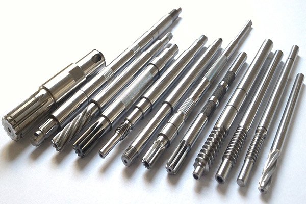
- Shaft
- Molds&Tools
- Hydraulics And Pump
- Hair transplant needle
- Hydraulics And Pump
- Precision CNC Shaft Machining Manufacturer for High Performance Applications
- Energy Industry CNC Machining Parts Supplier
- Aerospace Structural Components for OEM Programs
- Aerospace Structural Components for OEM Programs
- Automotive & EV CNC Machining Parts Supplier for OEM and Tier 1
- Medical Device CNC Machining Services
DFM for 5 Axis CNC Machining for Aerospace Parts: Reducing Risk Before Production


Complex aerospace components demand simultaneous five-axis movement to machine intricate geometries in titanium, Inconel and aluminum alloys. Yet even advanced 5 axis CNC machining for aerospace parts cannot overcome design features that block tool access, prevent inspection or lock in excessive cycle time. Design-for-manufacturability (DFM) for 5 axis CNC machining for aerospace parts shifts risk assessment upstream, where geometry, tolerance placement and feature sequencing decisions directly determine whether a part will scale from prototype to certified production without costly redesign.
Key Answer
DFM for 5 axis CNC machining for aerospace parts evaluates tool accessibility, fixture strategy, inspection visibility and material stability before the first cut. Early design review identifies features that require non-standard tooling, increase setup count or prevent CMM probe access, enabling geometry adjustments that reduce cycle time by 20–40 percent and eliminate late-stage redesign cycles that delay certification and production ramp.
Why DFM for 5 Axis CNC Machining for Aerospace Parts Differs from Conventional Mill Planning
Five-axis machining adds rotational freedom around A and B axes, enabling continuous tool orientation changes that reach undercuts, compound angles and deep pockets inaccessible to three-axis mills. This capability introduces new failure modes:
- Tool collision zones: The rotating head and trunnion table create exclusion volumes. A geometry valid in CAD may force the spindle housing into the fixture or workpiece.
- Fixture interference: Multi-sided access requires low-profile tombstones or custom soft jaws. Features that demand clamping on all six faces require mid-process re-fixturing and alignment verification.
- Material distortion: Removing 85 percent of billet mass in titanium or Inconel generates heat and internal stress. Unsupported thin walls bow; deep pockets twist. The five-axis capability does not eliminate the need for stress-relief cycles or strategic semi-finishing.
- Inspection access: AS9102 First Article Inspection reports require CMM verification of critical dimensions. Features positioned inside narrow cavities or behind undercuts may be unmeasurable without sectioning the part.
According to Five Flute’s DFM guidelines, standard end mills range from 3 mm to 25 mm diameter, with length-to-diameter ratios typically limited to 4:1 for rigid cutting. Aerospace parts frequently require longer tools to reach internal features, introducing deflection and chatter. DFM review highlights these zones early, allowing designers to widen access channels, reduce pocket depth or split the geometry across multiple components joined by mechanical fasteners.
Core DFM Considerations for Five-Axis Aerospace Machining
Tool Access and Reach
Evaluate every internal feature for straight-line tool approach. A 12 mm diameter tool with 60 mm length-to-diameter ratio will deflect under titanium cutting forces, producing poor surface finish and dimensional drift. Where possible:
- Increase internal fillet radii to match the largest standard cutter diameter that fits the feature envelope.
- Avoid sharp internal corners; specify radii equal to tool radius plus 0.5 mm clearance.
- Limit pocket depth to four times the cutter diameter unless the design accepts slower feeds and multiple roughing passes.
Tolerance Placement and Measurement Strategy
Tight positional tolerances on features hidden inside pockets or behind angled walls create inspection bottlenecks. CMM touch probes require line-of-sight access; optical systems need surface visibility. The tolerance and inspection framework used in aircraft structural components applies here: assign the tightest tolerances only to mating and load-bearing interfaces, and confirm that every toleranced feature allows probe access from at least two axes.
Fixture Strategy and Datum Stability
Five-axis parts often require 3+2 positioning (indexed five-axis) or continuous contouring (simultaneous five-axis). Both demand rigid, repeatable fixtures. Design considerations include:
- Incorporate datum features—flat pads, cylindrical bosses or precision holes—that remain accessible throughout the machining sequence.
- Avoid cantilevered overhangs exceeding five times the section thickness without intermediate support.
- Review part orientation in the fixture: a 15-degree rotation can expose all critical features to the spindle without re-clamping.
Material Selection and Removal Strategy
Titanium alloys (Ti-6Al-4V) and Inconel 718 dominate aerospace five-axis work due to strength-to-weight ratio and high-temperature performance. Both machine slowly and generate significant heat. Fictiv’s five-axis overview notes that simultaneous machining reduces setup count and improves geometric accuracy, but material behavior determines cycle time more than axis count. DFM review identifies stock removal sequences that balance roughing efficiency with thermal management, preventing distortion that pushes finish dimensions out of tolerance.
DFM Review Checklist for Five-Axis Aerospace Components
Use this checklist during design review sessions with manufacturing engineering before releasing drawings for quote:
- Tool clearance: Confirm that all internal features allow straight approach by standard-length cutters (L/D ≤ 4).
- Fillet radii: Match internal radii to available cutter diameters; avoid radii smaller than 1.5 mm unless functional requirements dictate otherwise.
- Tolerance mapping: Verify that every dimension tighter than ±0.05 mm permits CMM probe access without part disassembly.
- Datum accessibility: Ensure primary and secondary datums remain exposed and clampable through all operations.
- Thin-wall support: Flag any wall thinner than 1.5 mm or rib taller than 5:1 height-to-thickness for mid-process stress relief.
- Undercut necessity: Review every undercut and compound angle; eliminate those not driven by assembly or aerodynamic requirements.
- Re-fixturing count: Minimize setups by clustering features accessible from one or two orientations; each additional setup adds alignment error risk.
- Material stock size: Confirm that billet dimensions suit standard raw material sizes to avoid lead-time delays and scrap cost.
When to Escalate DFM Findings
Not every design adjustment fits within the OEM’s certification boundary. Escalate DFM concerns that affect:
- Structural load paths: Changing wall thickness or rib geometry may require re-analysis and FAA or EASA documentation updates.
- Interface dimensions: Alterations to bolt-hole patterns or mating surfaces trigger assembly cascade reviews across multiple components.
- Surface finish specifications: Roughness and waviness targets below Ra 0.8 μm demand additional grinding or super-finishing operations not always compatible with five-axis setups.
In these cases, the DFM report should quantify cost and schedule impact—cycle-time increase, additional setups, custom tooling expense—to support program management decisions on whether to accept higher manufacturing cost or initiate an engineering change.
Comparing Three-Axis and Five-Axis Geometry Constraints
| Design Feature | Three-Axis Constraint | Five-Axis Constraint |
|---|---|---|
| Undercut geometry | Not accessible; requires EDM or multiple setups | Accessible if tool collision volume clear |
| Internal fillet radius | Minimum = tool radius | Minimum = tool radius + clearance for entry angle |
| Thin-wall support | Requires backing fixtures | Reduced clamping force possible with better tool approach |
| Setup count | Typically 2–4 for complex parts | Often 1–2, but each setup more complex |
| Inspection access | Top and side features easy | Internal features may be blocked despite machining access |

Integrating DFM into the Aerospace Development Cycle
Effective DFM for five-axis aerospace parts occurs in three phases:
- Concept review: Share envelope models and key interface dimensions with manufacturing partners during preliminary design. Identify geometry families—pockets, ribs, holes—that will challenge tooling or fixtures.
- Detailed design review: Conduct formal DFM analysis on 80-percent-complete models. Use CAM simulation to detect collisions and measure tool deflection. Iterate geometry before finalizing drawings.
- Prototype debrief: After first article machining and inspection, document actual cycle time, setup difficulty and measurement challenges. Feed findings into production drawings and future designs.
This staged approach reduces the likelihood of discovering a blocking issue during first article inspection, when schedule pressure and certification deadlines leave little room for geometry changes.
Practical DFM Checklist for Procurement Teams
When reviewing quotes and supplier DFM feedback, verify that the analysis addresses:
- Specific tool selections and length-to-diameter ratios for deep or narrow features
- Fixture concepts and datum references for each setup
- Estimated cycle time broken down by roughing, semi-finishing and finishing operations
- Inspection plan with probe access confirmation for all critical dimensions
- Material removal percentage and recommended stress-relief intervals
- Any custom tooling or non-standard cutters required, with lead-time and cost impact
Suppliers with deep aerospace experience will volunteer this information; silence on these points signals insufficient process planning. Before committing to production tooling, request CAM simulation screenshots showing spindle clearance and tool engagement at critical features.
Frequently Asked Questions
What makes DFM for 5 axis CNC machining for aerospace parts different from general CNC DFM?
Five-axis DFM accounts for rotational collision zones, fixture visibility across multiple orientations and continuous tool-path optimization. Aerospace adds material traceability, tight tolerance documentation and AS9102 inspection requirements. Features must support both machining access and post-process measurement, which three-axis DFM often overlooks.
When should I involve the machine shop in the design review process?
Engage manufacturing engineering during preliminary design, ideally when the geometry concept is 60–70 percent defined. Early involvement allows geometry adjustments that avoid custom tooling and reduce setup count. Late-stage DFM reviews often identify blocking issues that require expensive engineering changes or compromise certification schedules.
How do I prioritize DFM findings when I cannot change every flagged feature?
Rank findings by impact on cycle time, setup count and inspection feasibility. Features that double machining hours, require custom fixtures or block CMM access warrant geometry changes. Minor improvements—slightly larger radii, relocated non-critical holes—can often wait for the next design iteration unless they offer significant cost reduction.
Does five-axis machining eliminate the need for multiple setups?
Not always. Complex parts with features on all six faces still require re-fixturing. Five-axis capability reduces setup count by reaching undercuts and angled features in one orientation, but clamping always obscures some surfaces. DFM review should target minimizing setups to two or fewer, balancing accessibility with fixture stability.
What internal corner radius should I specify for five-axis machined pockets?
Match the radius to the largest standard cutter diameter that fits the feature, typically 3 mm or larger. Smaller radii force the use of long, narrow tools that deflect under load, increasing cycle time and risking dimensional drift. If sharp corners are functionally required, consider secondary EDM operations identified during DFM review.
How does material choice affect DFM for five-axis aerospace parts?
Titanium and Inconel machine slowly and generate heat that distorts thin walls. DFM review for these materials emphasizes stock removal strategy, stress-relief timing and cutter engagement angles. Aluminum alloys machine faster but are softer, requiring careful clamping to prevent fixture marks. Material selection drives tooling, cycle time and fixturing decisions that DFM must address early.
Conclusion
DFM for 5 axis CNC machining for aerospace parts transforms geometry decisions into measurable manufacturing outcomes—cycle time, setup count, inspection feasibility and production cost. By evaluating tool access, tolerance placement and fixture strategy before releasing drawings, OEM engineering teams prevent late-stage redesign, reduce prototype iteration cycles and accelerate certification. Submit your design for detailed DFM feedback and manufacturability analysis tailored to five-axis aerospace production.