
- Shaft
- Molds&Tools
- Hydraulics And Pump
- Hair transplant needle
- Hydraulics And Pump
- Precision CNC Shaft Machining Manufacturer for High Performance Applications
- Energy Industry CNC Machining Parts Supplier
- Aerospace Structural Components for OEM Programs
- Aerospace Structural Components for OEM Programs
- Automotive & EV CNC Machining Parts Supplier for OEM and Tier 1
- Medical Device CNC Machining Services
DFM for Rapid CNC Prototyping: Reducing Risk Before Production

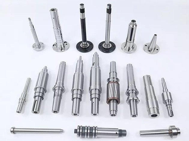
Design decisions made during rapid CNC prototyping directly determine manufacturability, inspection feasibility, and production scalability. Early application of DFM for rapid CNC prototyping prevents costly redesigns, reduces setup complexity, and validates production pathways before committing to tooling or volume runs. For OEM engineers and procurement teams managing prototype-to-production transitions, structured DFM analysis clarifies which geometric features, tolerance specifications, and material choices will translate efficiently from prototype batches to mass manufacturing.
Key answer: DFM for rapid CNC prototyping identifies design attributes that drive cost, lead time, and quality risk before production commitment. Early review of wall thickness, corner radii, tolerance placement, and fixturing requirements reduces prototype iteration cycles by 20-30% and prevents geometric constraints that complicate scale-up. Integrating manufacturability analysis during the prototype phase ensures parts can be inspected reliably, machined consistently across batch sizes, and adapted to volume production without fundamental redesign.
Why DFM Matters in the Prototype Phase
Prototyping validates form, fit, and function, but designs optimized only for a single prototype often fail when transitioning to multi-axis CNC production environments. According to research from manufacturing process experts, 70-80% of total product cost is locked in during the design phase, making early DFM intervention the most cost-effective risk mitigation strategy.
Common issues that emerge without prototype-phase DFM include:
- Features requiring custom tooling that cannot be justified at prototype volumes but become prohibitively expensive at scale
- Tolerance specifications tighter than functional requirements, increasing both prototype and production inspection burden
- Geometric constraints that force additional setups, extending cycle time by 30-40% per Protolabs design guidelines
- Material selections that machine efficiently in small batches but create tool wear or thermal stability issues in volume runs
These risks are preventable through structured design review before cutting the first prototype. Engineering teams that apply DFM analysis during CAD development report 20-30% cost reduction compared to designs submitted without manufacturability consideration, according to MakerStage benchmarking data.
Core DFM Principles for Rapid Prototyping
Geometry and Feature Accessibility
Machining accessibility determines setup count and tooling strategy. Deep pockets, narrow slots, and enclosed cavities that require extended-reach tooling increase both prototype cost and production risk. Standard end mill length-to-diameter ratios of 3:1 or 4:1 provide stable cutting conditions; exceeding 6:1 introduces chatter and dimensional variation.
Design guidelines from Hubs emphasize maintaining corner radii equal to or greater than tool diameter to eliminate EDM operations. Sharp internal corners require either wire EDM or dedicated corner-radius tooling, both of which extend prototype lead time and create production bottlenecks. Specifying 0.5mm or 1mm corner radii where functional requirements allow reduces tooling variety and enables standard machining workflows.
Tolerance Allocation and Inspection
Over-tolerancing—specifying tighter tolerances than functional requirements justify—increases both machining cost and inspection complexity. Each additional tolerance level typically adds 40-80% to part cost, according to cost modeling data. Prototype designs should distinguish between critical interfaces requiring tight control and non-functional surfaces where standard machining tolerances suffice.
For low-volume CNC production, geometric dimensioning and tolerancing (GD&T) provides clearer manufacturing intent than coordinate tolerances alone. Functional datum structures and positional tolerancing clarify inspection requirements and reduce ambiguity during prototype validation and production setup.
Material Selection and Machinability
Material choices affect tool life, cycle time, and thermal stability during machining. Aluminum alloys like 6061-T6 and 7075-T6 machine rapidly with excellent surface finish, making them ideal for functional prototypes requiring minimal post-processing. Stainless steels and titanium alloys require lower cutting speeds and generate higher tool wear, increasing both prototype and production costs.
For prototypes intended to validate production manufacturing processes, selecting the production-intent material during prototyping eliminates uncertainty about machinability, heat treatment response, and dimensional stability. This approach ensures prototype validation data transfers directly to production without material-related unknowns.
DFM Review Checklist for CNC Prototypes
Systematic design review before prototype fabrication prevents avoidable iteration. This checklist addresses the geometric, tolerance, and process attributes that most frequently drive prototype cost and production risk:
- Wall thickness: Maintain minimum 1mm walls for aluminum, 1.5mm for steel; thinner sections require specialized fixturing and introduce deflection risk
- Hole depth: Limit depth-to-diameter ratios to 5:1 for standard drilling; deeper holes require gun drilling or specialized processes
- Internal corners: Specify corner radii equal to or greater than smallest required cutter diameter; avoid sharp corners requiring EDM
- Tolerance specification: Apply tight tolerances only to functional interfaces; use standard machining tolerances (±0.1mm for general dimensions) elsewhere
- Surface finish: Specify Ra values only where functionally necessary; standard machined finishes (Ra 3.2–6.3 μm) avoid secondary operations
- Setup orientation: Design parts to minimize setups; each additional setup adds 30-40% to cycle time and introduces datum transfer error
- Fixturing: Provide adequate clamping surfaces; irregular geometries requiring custom soft jaws increase both prototype and production setup cost
- Thread specifications: Use standard thread forms and depths; custom or fine-pitch threads require dedicated tooling
This checklist can be applied during CAD review, before releasing drawings to manufacturing. Addressing these factors during design eliminates the most common sources of prototype delay and production scale-up difficulty.
Prototype-to-Production Transition Strategy
Effective DFM bridges prototype validation and production scalability. The transition from low-volume prototyping to volume production introduces different cost drivers, requiring design attributes that support both phases.
| Design Attribute | Prototype Impact | Production Impact | DFM Recommendation |
|---|---|---|---|
| Setup count | Moderate cost per setup | High cost multiplied by volume | Minimize setups; design for 3-axis when possible |
| Custom tooling | Can be justified for validation | Difficult to scale economically | Use standard tooling; avoid special form cutters |
| Tight tolerances | Manageable with careful work | Requires SPC and process capability | Tolerance only critical features |
| Material availability | Small quantities readily sourced | Lead time and cost sensitive at volume | Confirm material supply chain early |
Prototypes designed with production constraints in mind eliminate redesign cycles between validation and volume manufacturing. ISO-compliant manufacturing systems with ERP control enable smooth transitions when prototype designs already reflect production-capable geometry and tolerances.
Practical Application: Inspection and Validation
Prototype designs must accommodate the inspection methods that will be used in production. Features that cannot be measured reliably introduce quality risk regardless of machining capability. CMM accessibility, gauge design feasibility, and in-process inspection options should be evaluated during prototype DFM review.
Complex internal geometries may require CT scanning or specialized optical inspection, both of which add cost and lead time to production validation. Where possible, design parts so that critical dimensions can be verified with standard measuring tools—calipers, micrometers, bore gauges, and pin gauges. This approach reduces inspection cost and enables faster production feedback loops.
For functional prototypes used in aerospace or medical device applications, prototype inspection results establish the baseline for production process capability studies. Designs that facilitate clear, repeatable measurement during prototyping simplify the transition to statistical process control in volume manufacturing.
Common DFM Issues in Rapid Prototyping
Several design patterns recur frequently in prototype submissions and create unnecessary cost or risk:
- Undercuts requiring additional setups: Features accessible only from non-primary orientations force extra setups; redesigning for primary-axis accessibility reduces cycle time
- Excessive surface finish specifications: Specifying polished or ground finishes on non-functional surfaces adds secondary operations; reserve fine finishes for sealing surfaces and bearing journals
- Inconsistent wall thickness:Thin-to-thick transitions create thermal gradients and residual stress; uniform wall thickness improves dimensional stability
- Blind holes with tight depth tolerances: Depth control in blind holes is difficult and inspection-intensive; through-holes or relaxed depth tolerances reduce manufacturing difficulty
Identifying these issues during design review rather than after prototype fabrication prevents wasted iteration and accelerates validation timelines.

Frequently Asked Questions
What is the primary goal of DFM for rapid CNC prototyping?
The primary goal is to identify and resolve manufacturability constraints before committing to prototype fabrication, ensuring designs can be machined efficiently, inspected reliably, and scaled to production without fundamental redesign. Early DFM analysis reduces iteration cycles, controls prototype cost, and validates production pathways, preventing expensive changes after tooling or volume commitments are made.
How does DFM reduce prototype cost?
DFM reduces cost by eliminating unnecessary setups, avoiding custom tooling, relaxing non-functional tolerances, and simplifying fixturing requirements. Research shows DFM reviews reduce manufacturing cost by 20-30% compared to designs submitted without manufacturability analysis. Each eliminated setup saves 30-40% of cycle time, and tolerance rationalization avoids the 40-80% cost penalty associated with over-tolerancing.
Should prototypes use production-intent materials?
When prototypes are intended to validate manufacturing processes or functional performance under production conditions, using production-intent materials eliminates uncertainty about machinability, heat treatment response, and mechanical properties. For form-and-fit validation only, surrogate materials with similar machining characteristics can reduce prototype cost while confirming geometric feasibility before committing to more expensive production alloys.
What geometric features create the most production risk?
Deep pockets with high depth-to-width ratios, sharp internal corners, undercuts requiring secondary setups, and thin walls prone to deflection create the highest production risk. These features drive tool wear, extend cycle time, require specialized fixturing, and introduce dimensional variation. DFM review focuses on redesigning these features or confirming that their functional necessity justifies the manufacturing complexity.
How do tolerance specifications affect prototype-to-production transitions?
Tight tolerances specified on non-critical features increase both prototype and production cost without functional benefit. During production scale-up, tight tolerances require process capability studies, SPC implementation, and tighter process control. Allocating tight tolerances only to functional interfaces—mating surfaces, bearing fits, sealing diameters—simplifies manufacturing and reduces quality risk while maintaining performance requirements.
When should DFM analysis occur in the prototype development cycle?
DFM analysis should occur during CAD development, before releasing drawings for prototype fabrication. Early review allows geometric changes to be implemented at zero cost, while changes after machining begins require remanufacturing. Integrating DFM into the design process rather than treating it as a post-design review reduces iteration cycles and accelerates time to validated prototype.
Conclusion
Applying DFM for rapid CNC prototyping transforms prototype development from isolated validation into a strategic step toward scalable production. Structured review of geometry, tolerances, materials, and inspection requirements during the design phase prevents costly iteration, reduces prototype lead time, and ensures designs can transition smoothly to volume manufacturing. For engineering teams managing complex prototype-to-production programs, early DFM analysis is the most effective risk mitigation strategy, enabling confident scale-up decisions based on validated, production-ready designs. Submit your prototype drawings for manufacturability review and cost-effective fabrication planning.
Sources
- Protolabs Network (Hubs). Reduce the cost for CNC machining with instant DfM feedback. https://www.hubs.com/blog/reduce-the-costs-for-cnc-machining-with-instant-dfm-feedback/
- MakerStage. DFM Best Practices to Reduce Costs. https://www.makerstage.com/resources/dfm-best-practices
- Protolabs. Design for Machining Toolkit. https://www.protolabs.com/resources/design-for-machining-toolkit/