
- Shaft
- Molds&Tools
- Hydraulics And Pump
- Hair transplant needle
- Hydraulics And Pump
- Precision CNC Shaft Machining Manufacturer for High Performance Applications
- Energy Industry CNC Machining Parts Supplier
- Aerospace Structural Components for OEM Programs
- Aerospace Structural Components for OEM Programs
- Automotive & EV CNC Machining Parts Supplier for OEM and Tier 1
- Medical Device CNC Machining Services
Thin Wall CNC Turning Tolerances: A Practical Design and Inspection Guide

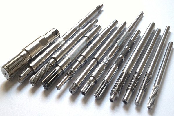
Thin wall CNC turning tolerances depend on wall thickness, material stiffness, workholding strategy, and the relationship between dimensional control and geometric features like concentricity. When wall thickness drops below 2 mm, thermal expansion, tool deflection, and part distortion begin to dominate the tolerance budget. Engineers designing sleeves, bushings, and tubular shafts need to understand which tolerances are achievable, which require secondary operations, and how inspection validates both dimensional and geometric compliance across production batches.
Key answer: Thin wall CNC turning tolerances are constrained by wall stiffness and clamping forces. Standard capabilities on walls under 2 mm typically range from ±0.05 to ±0.10 mm for diameter, with concentricity between 0.02 and 0.05 mm. Tighter results require optimized toolpaths, secondary machining, or in-process measurement. Material choice, wall-to-diameter ratio, and thermal stability during turning directly affect what you can hold in volume production.
How Wall Geometry Influences Achievable Thin Wall CNC Turning Tolerances
Wall thickness relative to part diameter determines deflection under cutting forces. A sleeve with 1.5 mm wall and 50 mm outer diameter behaves differently than a 1.5 mm wall on a 150 mm diameter. Lower wall-to-diameter ratios amplify radial deflection, making it harder to maintain roundness and concentricity during the turning cycle.
Protolabs notes that standard CNC machining tolerances are ±0.125 mm, but thin walls often require tighter control to preserve function. When the wall deflects under the cutting tool, the measured diameter after release differs from the in-cut dimension, introducing variability that shows up during CMM inspection.
Geometric tolerances—particularly concentricity and cylindricity—become limiting factors before dimensional tolerances. A thin-walled shaft may meet diameter specifications but fail concentricity between inner and outer diameters due to uneven material removal or thermal gradients during the turning operation.
Material Properties and Their Effect on Turned Tolerances
Material stiffness and thermal expansion coefficient directly influence tolerance capability. Aluminum alloys offer good machinability but expand significantly with heat, requiring careful coolant delivery and reduced feed rates to control dimensional drift. Stainless steels provide better thermal stability but generate higher cutting forces, increasing deflection risk on thin walls.
Parkway Kew highlights that thin wall lathe parts demand tailored techniques because standard approaches introduce too much deflection. Harder materials like titanium or hardened steel magnify this challenge, often requiring carbide or CBN tooling and reduced depth of cut to maintain tolerance windows.
- Aluminum 6061-T6: Good machinability, moderate deflection, thermal expansion requires coolant control
- Stainless 304/316: Higher cutting forces, better dimensional stability under heat
- Titanium Ti-6Al-4V: Low thermal conductivity concentrates heat at the tool-part interface, complicating thin wall work
- Brass and bronze: Excellent machinability, reduced spring-back after tool release
Process Control: Workholding, Toolpath Strategy, and Cutting Parameters
Workholding design for custom motor shafts and thin-walled components must balance clamping force with distortion risk. Soft jaws, expanding mandrels, or hydraulic collets distribute force more evenly than standard three-jaw chucks, reducing out-of-round conditions.
Toolpath strategy matters. Finishing passes with reduced depth of cut—often 0.1 to 0.2 mm—and controlled feed rates minimize deflection. Multi-pass strategies allow heat dissipation between cuts, preserving dimensional stability. Climb milling or balanced roughing-finishing cycles reduce residual stress that can warp the part after release.
Cutting parameters for thin walls differ from solid shaft turning. Spindle speeds increase to maintain surface speed while reducing radial cutting forces. Coolant delivery—preferably through-spindle or high-pressure flood—controls temperature and chip evacuation, both critical for thin wall CNC turning operations.
Comparison of Typical Tolerance Capabilities by Wall Thickness
| Wall Thickness | Diameter Tolerance | Concentricity Tolerance | Process Notes |
|---|---|---|---|
| >3 mm | ±0.025 mm | 0.01–0.02 mm | Standard turning, moderate clamping |
| 2–3 mm | ±0.05 mm | 0.02–0.03 mm | Optimized toolpath, soft jaws recommended |
| 1–2 mm | ±0.08 mm | 0.03–0.05 mm | Multi-pass finishing, thermal control essential |
| <1 mm | ±0.10 mm or wider | 0.05 mm or wider | Secondary operations often required |

Inspection Methods and Evidence of Compliance
Verifying thin wall CNC turning tolerances requires measurement techniques that do not distort the part. CMM inspection with low-force probes or non-contact optical scanning provides diameter, concentricity, and cylindricity data without inducing deflection. Air gauging works well for inner diameters where probe access is limited.
Concentricity inspection demands a datum reference, typically the outer diameter or a machined shoulder. Runout measurements on a precision spindle or between centers reveal geometric deviations that affect assembly fit. For high-volume production, statistical process control tracks diameter and concentricity trends, flagging tool wear or thermal drift before parts leave specification.
First article inspection (FAI) and in-process checks validate that setup, tooling, and parameters deliver the required tolerances. Production batches benefit from periodic sampling, with CMM reports documenting diameter, concentricity, surface finish, and any geometric deviation across the lot.
Design Checklist for Specifying Thin Wall Turned Components
- Define wall thickness and diameter clearly; avoid wall-to-diameter ratios below 0.02 unless secondary support is feasible
- Specify diameter tolerances appropriate to wall stiffness—consult your supplier early if tighter than ±0.05 mm is required
- Call out concentricity between inner and outer diameters with a realistic datum and tolerance zone
- Identify material with thermal expansion and machinability in mind
- Consider how the part will be clamped and whether soft jaws or mandrels are necessary
- Request FAI with CMM data showing diameter, concentricity, and surface finish before committing to full production
- Plan for inspection methods that do not deform the part during measurement
When to Engage Your Manufacturing Partner Early
Thin wall components benefit from early supplier involvement. CNC machining capabilities vary widely, and a shop experienced in aerospace or medical thin-wall work brings process knowledge that avoids costly design revisions.
If your application requires long shaft tolerances or combines thin walls with complex features, request a manufacturability review during the design phase. Suppliers can model deflection, recommend material substitutions, or suggest geometry changes that preserve function while improving tolerance capability and cost.
Frequently Asked Questions
What is the tightest diameter tolerance achievable on a 1.5 mm wall turned part?
For a 1.5 mm wall, diameter tolerances of ±0.05 to ±0.08 mm are typically achievable with optimized toolpaths and proper workholding. Tighter tolerances—down to ±0.03 mm—may require secondary grinding or honing operations, depending on material and geometry. Wall stiffness and thermal control during turning are the primary limiting factors.
How does concentricity differ from runout in thin wall CNC turning tolerances?
Concentricity measures how closely the axis of one feature aligns with the axis of a datum feature, independent of surface irregularities. Runout combines concentricity and surface form errors, measuring total variation as the part rotates. For thin walls, concentricity is the more demanding control because it isolates geometric alignment, which is critical for shafts, sleeves, and bearing journals.
Can you improve thin wall turning tolerances with post-machining operations?
Yes. Cylindrical grinding, honing, or superfinishing can tighten diameter and cylindricity tolerances after turning. These operations remove minimal material and reduce the influence of turning deflection. However, they add cost and lead time, so optimizing the turning process first is usually more cost-effective for volume production.
What inspection method is best for verifying thin wall CNC turning tolerances without distorting the part?
Non-contact optical scanning or CMM inspection with low-force probes prevents measurement-induced distortion. Air gauging works well for internal diameters. Avoid clamping or probing methods that apply significant radial force, as they can temporarily deform the part and produce false readings, especially on walls under 2 mm.
How does material selection affect achievable tolerances on thin-walled turned components?
Stiffer materials with lower thermal expansion—such as stainless steel or brass—generally support tighter tolerances than aluminum, which expands more with heat. However, harder materials increase cutting forces and tool wear, requiring process adjustments. Material choice should balance machinability, stiffness, thermal behavior, and the functional requirements of the finished part.
When should I request a first article inspection for thin wall turned parts?
Request FAI whenever wall thickness is below 2 mm, tolerances are tighter than ±0.08 mm, or concentricity requirements are specified. FAI with CMM documentation verifies that the manufacturing process meets design intent before committing to full production, reducing risk of costly rework or assembly issues downstream.
Conclusion
Thin wall CNC turning tolerances result from the interaction of geometry, material properties, process control, and inspection rigor. Understanding how wall-to-diameter ratios, cutting forces, and thermal effects influence dimensional and geometric outcomes allows you to specify realistic tolerances and engage suppliers with the right capabilities. For applications demanding tight concentricity, controlled diameter, and batch consistency, early collaboration and evidence-based inspection are essential. Upload your drawing to discuss how your thin-walled shaft or sleeve can be manufactured to specification.