- Shaft
- Molds&Tools
- Hydraulics And Pump
- Hair transplant needle
- Hydraulics And Pump
- Precision CNC Shaft Machining Manufacturer for High Performance Applications
- Energy Industry CNC Machining Parts Supplier
- Aerospace Structural Components for OEM Programs
- Aerospace Structural Components for OEM Programs
- Automotive & EV CNC Machining Parts Supplier for OEM and Tier 1
- Medical Device CNC Machining Services
DFM for Thin Wall CNC Turning: Reducing Risk Before Production

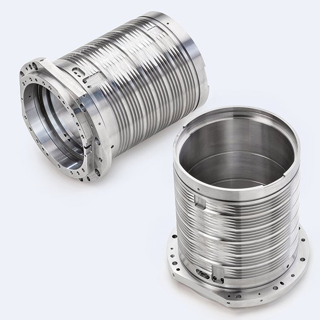
Thin-walled turned components—shafts, sleeves, and bushings with wall thicknesses below 2 mm—are essential in aerospace actuators, medical devices, and precision robotics. Yet these parts concentrate manufacturing risk: even small design oversights lead to deflection during machining, difficulty holding concentricity, and inspection challenges that delay production. Applying DFM for thin wall CNC turning early in the design phase prevents these issues by aligning geometry, material, and tolerance decisions with the realities of the lathe.
Key Answer
DFM for thin wall CNC turning addresses deflection, vibration, and measurement access by constraining wall thickness ratios, length-to-diameter proportions, and tolerance placement. Early collaboration between design and manufacturing teams reduces scrap, shortens cycle time, and enables stable batch production. Decisions made at the CAD stage—material hardness, feature sequence, and datum strategy—determine whether a part can be turned economically at scale.
Why Thin Wall Turning Demands Early DFM Attention
Thin walls amplify precision shaft machining challenges. Cutting forces that are trivial on solid bar stock cause measurable deflection when wall thickness drops below 1.5 mm. That deflection translates directly into poor concentricity, surface waviness, and tolerance violations. Traditional post-design optimization cannot fix geometric constraints baked into the CAD model, making upfront DFM discipline essential.
Common failure modes include:
- Chatter and vibration: Long unsupported sections resonate under tool pressure, degrading surface finish and tool life.
- Dimensional drift: Clamping and thermal expansion distort thin walls, shifting dimensions between operations.
- Inspection inaccessibility: Internal features and tight bores prevent CMM probe access, forcing less capable gaging methods.
- Scrap spikes during scale-up: Parts that pass prototype validation fail when batches reach 100+ units due to accumulated process variation.
Material Selection and Machinability Trade-Offs
Material choice directly affects achievable wall thickness and production cycle time. Aluminum alloys (6061-T6, 7075-T6) machine quickly and tolerate walls down to 0.8 mm with proper toolpath strategy. Stainless steels (303, 316) require slower feeds and generate more heat, limiting practical minimum wall thickness to 1.2 mm. Hardened alloys and exotic materials such as Inconel demand ceramic or carbide tooling and may push minimum walls to 1.5–2.0 mm to maintain process stability.
Designers should verify material hardness and machinability early. A material substitution late in the cycle often forces tolerance relaxation or geometry changes that cascade into other assemblies.
Geometric Guidelines That Reduce Deflection Risk
Protolabs and other experienced suppliers recommend length-to-diameter (L/D) ratios below 3:1 for unsupported turned sections to minimize deflection. When ratios exceed 4:1, consider intermediate support, tailstock engagement, or splitting the part into two bonded or threaded assemblies.
Wall thickness uniformity matters. Abrupt changes in wall thickness concentrate stress and complicate toolpath generation. Gradual transitions—radii at least 1.5× the minimum wall thickness—distribute cutting forces and reduce the chance of breakthrough or distortion.
Key geometric rules:
- Maintain wall thickness ≥ 1.0 mm for aluminum, ≥ 1.5 mm for stainless steel and harder alloys.
- Avoid sharp internal corners; use radii ≥ 0.5 mm to reduce tool deflection and improve chip evacuation.
- Limit bore depth to 3× bore diameter without pilot drilling or gun drilling.
- Provide external reference surfaces for secondary operations to preserve concentricity.
Tolerance Placement and Datum Strategy
Concentricity, perpendicularity, and runout tolerances are difficult to verify on thin walls. A thin wall CNC turning tolerance tighter than ±0.02 mm often requires post-machining measurement on a dedicated fixture, adding cost and cycle time. Instead, use geometric dimensioning and tolerancing (GD&T) to specify functional requirements relative to stable datums—typically the largest diameter or a face perpendicular to the axis.
Avoid stacking tolerances across multiple diameters. Cumulative error grows quickly in multi-step turning operations, especially when parts are rechucked. Consolidate critical dimensions into a single setup whenever possible, and specify inspection points that are accessible with standard CMM or indicator gages.
DFM Decision Framework for Thin Wall Shafts
| Design Parameter | Low Risk (Recommended) | High Risk (Requires Justification) |
|---|---|---|
| Wall Thickness (Aluminum) | ≥ 1.2 mm | < 1.0 mm |
| Wall Thickness (Stainless) | ≥ 1.5 mm | < 1.2 mm |
| Length-to-Diameter Ratio | ≤ 3:1 | > 4:1 |
| Internal Corner Radius | ≥ 0.5 mm | Sharp (0.1 mm or less) |
| Concentricity Tolerance | ≥ 0.03 mm | < 0.02 mm |
| Surface Finish (Ra) | ≥ 1.6 µm | < 0.8 µm |
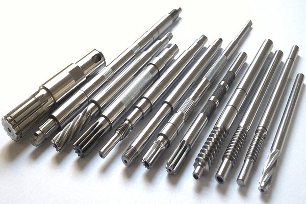
Fixturing and Setup Considerations
Thin walls collapse under excessive clamping force, introducing dimensional error that persists through all downstream operations. Soft jaws, expanding mandrels, and hydraulic collets distribute clamping pressure more evenly than standard three-jaw chucks. For very thin walls (< 1.0 mm), consider machining in the semi-finished state with extra material, then removing support stock in a final operation after stress relief.
Multi-axis or Swiss-type lathes with guide bushings provide continuous support near the cutting zone, enabling longer, thinner geometries than conventional turning centers. Evaluate machine capability during the design phase; a part that requires Swiss-style support cannot be economically produced on a standard lathe.
Balancing Cost and Manufacturability
Tighter tolerances, thinner walls, and more complex geometries all increase thin wall CNC turning cost through longer cycle times, more frequent tool changes, and higher scrap rates. MakerStage reports that strategic DFM adjustments can reduce manufacturing costs by 20–30% by eliminating features that require specialized tooling or secondary operations.
Cost-reduction opportunities include:
- Relaxing non-critical tolerances from ±0.01 mm to ±0.02 mm.
- Standardizing bore diameters to match available tooling.
- Removing undercuts or internal threads that require form tools.
- Specifying standard surface finishes (Ra 1.6 µm or 3.2 µm) rather than custom polishing.
Early collaboration between design and manufacturing teams identifies these trade-offs before tooling is ordered or production begins.

Pre-Production DFM Checklist
- Verify material machinability and availability in required bar stock diameters.
- Confirm wall thickness meets minimum guidelines for the selected material and machine type.
- Check length-to-diameter ratios and plan intermediate support if needed.
- Review tolerance stack-ups and assign datums to stable, accessible surfaces.
- Ensure critical dimensions are measurable with standard inspection equipment.
- Identify features that require form tools, special inserts, or secondary operations.
- Request CNC machining capability review from your manufacturing partner before finalizing drawings.
- Conduct first-article inspection to validate concentricity, runout, and surface finish before batch production.
Frequently Asked Questions
What is the minimum wall thickness for thin wall CNC turning?
Minimum practical wall thickness depends on material and machine capability. Aluminum can be turned to 0.8–1.0 mm with proper tooling and support. Stainless steel typically requires 1.2–1.5 mm. Harder alloys and exotic materials may need 1.5–2.0 mm to prevent deflection and chatter. Always confirm limits with your manufacturing partner based on specific geometry and tolerance requirements.
How does DFM for thin wall CNC turning differ from standard turning DFM?
Thin wall DFM emphasizes deflection control, fixturing strategy, and inspection access. Standard turning focuses on tool access, chip evacuation, and cycle time. Thin walls require tighter constraints on length-to-diameter ratios, more careful tolerance placement, and often specialized equipment such as Swiss-type lathes or soft-jaw fixturing to prevent distortion during machining.
Can tight concentricity tolerances be achieved on thin-walled shafts?
Yes, but it requires careful setup and often single-chucking to avoid datum shift. Concentricity tolerances below 0.02 mm are difficult to verify and manufacture on walls thinner than 1.5 mm. Use datum references on stable external diameters, specify runout relative to functional surfaces, and plan for CMM or indicator inspection on a dedicated fixture. Long shaft turning DFM principles also apply when length compounds deflection risk.
Should I specify surface finish requirements on thin walls?
Specify only the surface finish required for function. Standard finishes (Ra 1.6 µm or 3.2 µm) are achievable with sharp carbide inserts and moderate speeds. Finer finishes (Ra 0.8 µm or better) may require grinding or polishing, adding cost and complexity. Thin walls amplify vibration, making very fine finishes difficult to maintain in production. Discuss finish requirements with your machining partner during design review.
How do I prevent distortion during thin wall turning?
Use soft jaws or expanding mandrels to distribute clamping force evenly. Machine in multiple light passes rather than heavy cuts. Maintain consistent coolant flow to control thermal expansion. For walls below 1.0 mm, consider leaving temporary support material and removing it in a final operation after stress relief. Guide bushings and tailstock support also reduce deflection on longer parts.
When should I involve manufacturing in the design process?
Involve manufacturing as early as concept design, especially for thin-walled components with tight tolerances. Early collaboration identifies material constraints, machine limitations, and tolerance feasibility before drawings are finalized. A design review at 30–50% completion allows geometry changes without rework. Submit drawings for DFM feedback before committing to tooling or production orders.
Conclusion
Applying DFM for thin wall CNC turning during the design phase prevents deflection, reduces scrap, and enables stable batch production. Wall thickness, material selection, tolerance placement, and fixturing strategy must align with machine capability and inspection feasibility. Early collaboration between design and manufacturing teams identifies trade-offs, reduces cost, and shortens time to production. When thin-walled shafts and sleeves are designed with manufacturing constraints in mind, they move from prototype to scale-up without the delays and rework that plague parts designed in isolation.
Sources
- Protolabs: Design for Machining Toolkit
- MakerStage: DFM Best Practices to Reduce Costs