
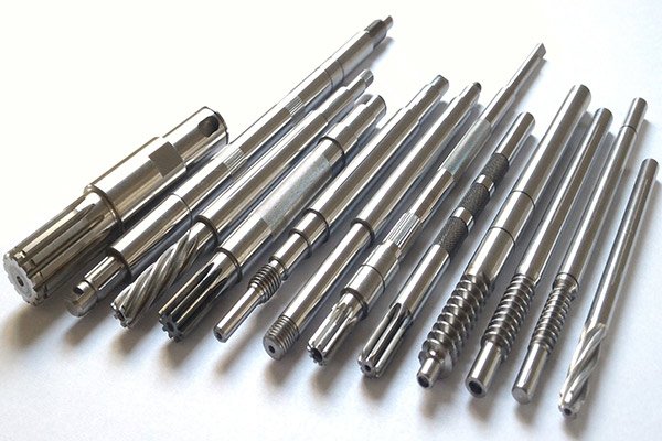
- Shaft
- Molds&Tools
- Hydraulics And Pump
- Hair transplant needle
- Hydraulics And Pump
- Precision CNC Shaft Machining Manufacturer for High Performance Applications
- Energy Industry CNC Machining Parts Supplier
- Aerospace Structural Components for OEM Programs
- Aerospace Structural Components for OEM Programs
- Automotive & EV CNC Machining Parts Supplier for OEM and Tier 1
- Medical Device CNC Machining Services
DFM for Large Format CNC Milling: Reducing Risk Before Production


Design-for-manufacturability (DFM) for large format CNC milling is the discipline of embedding production reality into your part geometry, tolerances, and material choices before tooling or first articles are cut. For OEM engineers and sourcing teams, this means catching expensive design conflicts early—when a CAD change costs nothing, not when a $50k aluminum pocket requires scrap and rework.
Key answer: Large format milling introduces rigid constraints: tool reach, spindle power, fixture accessibility, and thermal stability all shift at scale. Early DFM analysis of draft angles, pocket depth-to-width ratios, datum references, and surface finish zones prevents production bottlenecks, inspection failures, and non-conformance discoveries after first articles ship.
Why DFM Matters for Large Format CNC Milling
Large format CNC milling—typically parts exceeding 500 mm in any dimension—operates under different physical rules than small-part machining. Machine deflection, thermal growth, tool breakage risk, and fixturing complexity all rise with workpiece size. A design choice that works on a 100 mm part may be impossible or cost-prohibitive on a 2-meter casting.
Design-for-manufacturability applied early catches these mismatches:
- Eliminates tool collisions and spindle overload scenarios before CAM programming
- Ensures datum surfaces are accessible and repeatable for measurement
- Reduces scrap from thermal growth or spindle chatter in deep pockets
- Simplifies fixturing, shortening setup time and improving batch consistency
From prototype to mass production, multi-axis CNC solutions require this discipline at every scale boundary. Skipping DFM analysis in the design phase typically costs 15–40% more in production labor and 10–30% longer lead times.
Core DFM Rules for Aluminum and Large Format Parts
Pocket Depth and Wall Thickness
A milled pocket that is deeper than 5 times its width creates severe risk: tool deflection increases exponentially, chatter becomes uncontrollable, and surface finish suffers. For aluminum large format parts, the industry standard is a 4:1 depth-to-width ratio maximum. If your design requires a deeper pocket, redesign the geometry—split it into stages, add intermediate ledges, or reconsider the feature entirely.
Practical rule: If a pocket is 100 mm wide, limit depth to 400 mm. For depths beyond this, consult with your CNC shop early; expect cost and schedule impact.
Draft Angles and Wall Taper
Vertical walls in aluminum large format parts sound simple but introduce tool flex and surface finish inconsistency. A 2–3 degree outward draft (taper) on interior walls dramatically improves surface finish and reduces tool wear. On exterior surfaces, 1–2 degrees is sufficient and often invisible to end-users.
Without draft, the same tool must cut from root to top of the wall under changing engagement conditions, leading to chatter marks and rework.
Fillet Radii and Sharp Corners
Sharp internal corners (zero radius) require a corner-radius tool or multiple passes. For large format aluminum milling, specify internal radii of at least 2–3 mm; external radii should be 1–2 mm minimum. This single choice cuts tool changeovers and speeds cycle time by 10–20%.
Specify these radii in your CAD model or 2D drawing callout. Leaving them unspecified forces the CNC programmer to guess, risking non-conformance or cost overruns.
Tolerance and Datum Strategy for Large Format Parts
On large format CNC milling, tolerances tighten predictably only when referenced to a stable datum that the machine can hold. Thermal growth, spindle runout, and fixturing repeatability all affect what you can actually achieve.
Datum Surface Selection
Designate one primary datum surface—typically the largest, flattest face that clamps directly to the machine vise or fixture. This surface should be milled first or relieved (skimmed) before secondary features are cut. All critical features should be toleranced relative to this datum, not to adjacent features.
Bad practice: Tolerancing a pocket depth from the bottom face of the part, which may not have been milled yet.
Good practice: Tolerancing pocket depth from the primary datum surface established in setup 1, then measuring after all features are complete.
GD&T Callouts for Inspection
Large format parts destined for Tier 1 or aerospace assembly require geometric dimensioning and tolerancing (GD&T) that is unambiguous. Specify perpendicularity to the datum, not just +/– tolerance. Call out runout if the feature must be concentric to a bore. Specify flatness if a clamping or seal face matters.
These callouts save time during CMM (coordinate measuring machine) inspection and prevent acceptance/rejection disputes downstream.
Material and Surface Finish Implications
Aluminum is the workhorse of large format CNC milling—it machines predictably, dissipates heat well, and offers good strength-to-weight. However, tool engagement and cutting speed must be carefully tuned.
- Cutting speed: Aluminum tolerates faster spindle speeds than steel (300–600 SFM), but on large format machines with 10–40 kW spindles, feed rates must be adjusted to avoid deflection
- Chip evacuation: Long aluminum chips can wrap around tools in large pockets; specify through-coolant machining or chip breakers in CAM to prevent tool damage
- Surface finish zones: Identify which surfaces require fine finish (Ra 0.8–1.6 µm for bearing faces) and which can be as-milled (Ra 3.2–6.4 µm). Calling out unnecessary finish drives unnecessary cost
Precision manufacturing systems optimize cutting parameters automatically when part geometry is DFM-compliant, but non-compliant designs force manual CAM rework and slow production.
Fixturing and Accessibility Analysis
Before releasing a large format design to the shop floor, verify that every critical feature can be reached by a tool and inspected by a probe.
Tool Reach Checklist
- Spindle clearance: On a vertical CNC, the spindle head must not collide with clamps, parallels, or the part during tool motion
- Pocket accessibility: Deep pockets may require a custom tool holder; shallow pockets may accept standard geometry
- Undercuts and overhangs: Avoid any geometry that requires horizontal tool approach on a 3-axis machine. If unavoidable, plan for 4- or 5-axis setup
Measurement and Datum Accessibility
CMM inspection requires unobstructed probe access to critical surfaces. If a datum surface is blocked by bosses or ribs, the part cannot be measured accurately. Discuss inspection strategy with your CNC partner before release.
DFM Checklist for Large Format Milling
Before submitting your design for quotation:
- Verify all pockets: depth ≤ 4 × width for aluminum
- Specify internal fillet radii ≥ 2 mm, external ≥ 1 mm
- Add 2–3° draft to interior vertical walls
- Identify and label the primary datum surface
- Call out GD&T for critical features (perpendicularity, runout, flatness)
- Distinguish finish zones: call out only surfaces requiring fine finish
- Verify tool approach: sketch spindle position relative to all features
- Confirm fixturing: identify clamping surfaces and vise jaw geometry
- Review assembly interfaces: ensure datum surfaces align with mating parts
- Document any undercuts, overhangs, or multi-setup requirements
When to Involve Your CNC Partner Early
Design-for-manufacturability is most valuable as a design consultation, not a rejection mechanism. The best OEM–supplier relationships involve the shop floor in the design-review phase, before CAD is locked. For large format parts, flag these scenarios early:
- Any feature requiring multiple tool changes or setups
- Pockets or bores with tight runout or flatness tolerances
- Materials harder than aluminum (steel, titanium, cast iron) or brittle materials (ceramics)
- Tight dimensional stacks or secondary datum references
- First-article inspection with high-precision CMM requirements
Upload your drawings for a detailed quote and DFM feedback, or contact our engineering team to review your design before finalization.
Frequently Asked Questions
What is the difference between DFM and Design for Assembly (DFA)?
DFM focuses on the part-level production process: geometry, tooling, fixturing, and inspection. DFA addresses how multiple parts fit together in assembly. Both matter; DFM is the foundation. A part that is DFM-compliant but poorly integrated into assembly will still cause supply chain friction.
Can I specify zero-radius corners to reduce material?
Mathematically yes, but practically no for large format CNC milling. Zero-radius corners require custom corner tools or multiple passes, both adding cost and cycle time. Specify a 2–3 mm radius and accept the minimal material penalty; the production savings pay for it in volume.
How tight can tolerances be on large format aluminum parts?
Aluminum large format parts can hold ±0.05 mm on datum-referenced features with 3-axis machining. Tighter tolerances (±0.02 mm or better) require 5-axis capability or grinding operations, both adding cost. Discuss your tolerance stack-up with your CNC partner; often, looser tolerances on non-critical features free up tighter tolerance budget where it matters.
Should I specify surface finish (Ra) on all surfaces?
No. Over-specifying finish drives unnecessary cost. Call out Ra values only on surfaces that contact fluids, seal, conduct electricity, or are visible in assembly. As-milled aluminum (Ra 3.2–6.4 µm) is acceptable for most structural surfaces.
What happens if my design is not DFM-compliant when I submit it?
The shop will flag non-conformances in the quote, request a design change, or propose a workaround (multi-setup, hand-finishing, or premium tooling). Each adds cost or lead time. Catching these issues during design review—not after quoting—keeps your project on schedule.
Is DFM relevant for prototype orders, or only for production?
DFM is crucial for both. A prototype built on poor design decisions will reveal costly rework cycles; worse, it may be non-representative of production, delaying launch. Build DFM discipline into prototype design. It pays back in faster design iteration and predictable production transition.
Conclusion
Design-for-manufacturability for large format CNC milling is the difference between a design that moves to production smoothly and one that stalls in CAM, rework, or first-article failure. The core rules are simple: limit pocket depth ratios, specify draft and fillet radii, reference tolerances to stable datums, and verify tool access before you release to the shop.
DFM for large format CNC milling works best as a collaborative discipline, not a checklist. Invite your CNC partner into the design review phase. The cost of that conversation—zero. The cost of discovering design conflicts after quoting or first article—often 20–40% of production savings and weeks of delay.
Sources:
- Protolabs. “Design for Machining Toolkit.” https://www.protolabs.com/resources/design-for-machining-toolkit/
- Five Flute. “CNC Machining DFM – Design Guidelines for Milled Parts.” https://www.fiveflute.com/guide/cnc-machining-dfm-design-guidelines-for-milled-parts/
- HPPI. “What is DFM?” https://hppi.com/knowledge-base/dfm