
- Shaft
- Molds&Tools
- Hydraulics And Pump
- Hair transplant needle
- Hydraulics And Pump
- Precision CNC Shaft Machining Manufacturer for High Performance Applications
- Energy Industry CNC Machining Parts Supplier
- Aerospace Structural Components for OEM Programs
- Aerospace Structural Components for OEM Programs
- Automotive & EV CNC Machining Parts Supplier for OEM and Tier 1
- Medical Device CNC Machining Services
DFM for Shaft Grinding: Reducing Risk Before Production

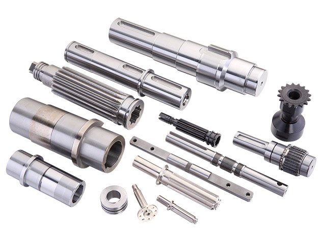
Shaft grinding delivers the tight tolerances and superior surface finishes required for precision mechanical assemblies, but manufacturability problems often emerge late in the development cycle when design corrections are expensive. Applying design-for-manufacturability principles early—before drawings are released—reduces rework, shortens lead times, and ensures that ground shafts meet functional requirements at scale.
Key answer: DFM for shaft grinding involves evaluating geometric features, material selection, tolerance stacks, and inspection access during the design phase. Early engagement with manufacturing engineers identifies grinding limitations, optimizes datum schemes, and balances surface finish requirements with production cost. This approach prevents costly design changes after tooling investment and accelerates the path from prototype to volume production.
Why DFM Matters in Shaft Grinding
Grinding is a finishing process that removes small amounts of material to achieve precision, but it cannot correct poor design decisions. Shafts with inaccessible features, unrealistic tolerance zones, or incompatible material properties create bottlenecks during grinding, inspection, and assembly. According to PEKO Precision’s DFM guidelines, manufacturability reviews during the design phase reduce production costs by 20-40% compared to post-prototype corrections.
For components destined for hydraulic pump assemblies, aerospace actuators, or precision robotics, grinding tolerances often fall below 5 microns with surface finishes finer than Ra 0.4 µm. Missing a datum reference, specifying an unmeasurable roundness tolerance, or selecting a material prone to grinding cracks can delay production by weeks and trigger expensive redesigns.
Core DFM Considerations for Ground Shafts
Material Selection and Grindability
Not all materials grind equally. Hardened alloy steels (52-62 HRC) are standard for bearing journals and spline shafts, but certain grades exhibit grinding burns or residual stress cracking if thermal management is inadequate. Austenitic stainless steels tend to smear rather than cut cleanly, requiring specialized wheels and slower feed rates that increase cycle time.
Designers should confirm material hardness ranges and thermal properties with the manufacturing partner before finalizing the specification. For example, through-hardened 4140 or case-hardened 8620 both support tight tolerances, but 8620 requires carburizing before grinding, adding process steps and cost.
Tolerance Stacks and Datum Schemes
Grinding operations depend on stable workholding and repeatable datum references. Shafts clamped between centers require a center-drilled hole at each end; those held in chucks need a ground reference diameter or face. When multiple diameters must maintain tight concentricity, the datum scheme should minimize stack-up and allow single-setup grinding whenever possible.
Specifying a flatness tolerance on a face that will be used as a datum is essential. If the primary datum is rough-machined only, grinding secondary features to tight positional tolerances becomes impractical. The LibreTexts DFM guide emphasizes that clear, hierarchical datum structures reduce setup variation and improve first-pass yield.
Surface Finish and Roundness Requirements
Ground surface finishes range from Ra 0.2 µm for precision bearing journals to Ra 0.8 µm for general motion-control shafts. Specifying finer finishes than necessary increases grinding time and wheel dressing frequency, raising cost without functional benefit. Roundness tolerances should align with bearing or seal requirements; typical ranges are 2-5 microns for industrial applications and below 1 micron for high-speed or ultra-precision assemblies.
Designers should also consider the interplay between surface finish and functional coatings. If the shaft will receive a hard-chrome or PVD coating after grinding, the post-coating finish and dimensional change must be factored into the pre-grinding specification.
Design Features That Complicate Grinding
- Interrupted surfaces: Keyways, cross-holes, and flats disrupt the grinding wheel path, causing chatter and uneven finish. When possible, locate these features outside critical tolerance zones or add stress-relief radii.
- Thin sections: Shafts with large diameter-to-length ratios or thin walls deflect under grinding pressure, making it difficult to hold roundness. Ribbing, intermediate supports, or reduced grinding depth-of-cut may be required.
- Sharp internal corners: Grinding wheels have finite radii. Internal fillets smaller than the wheel radius cannot be ground and require secondary EDM or broaching operations.
- Undercuts and relief grooves: While these features aid assembly, they must be accessible to the grinding wheel. Blind undercuts or grooves too narrow for wheel clearance force alternative machining methods.
Inspection Access and Measurement Strategy
A shaft design is only as manufacturable as it is inspectable. Roundness, cylindricity, and surface finish are typically verified on dedicated metrology equipment—coordinate measuring machines (CMMs) or form testers—but the shaft geometry must allow probe access. Long, slender shafts may require custom fixturing to prevent sag during measurement, adding inspection time and cost.
For components in aerospace applications, traceability and statistical process control (SPC) are mandatory. Designers should specify critical characteristics clearly and allocate tolerance zones that can be measured repeatably. When possible, avoid tolerances that require specialized gauges or indirect measurement methods, as these increase both cycle time and uncertainty.

DFM Review Framework for Shaft Grinding Projects
| Design Element | DFM Checkpoint | Risk if Ignored |
|---|---|---|
| Material specification | Confirm hardness range, grindability, and thermal stability | Grinding burns, cracking, or excessive cycle time |
| Datum scheme | Verify datum features are ground or finish-machined | Poor concentricity, high setup variation |
| Tolerance allocation | Align tolerances with grinding capability and inspection access | Unverifiable specs, high scrap rate |
| Surface finish | Match finish to functional requirements, not arbitrary targets | Increased cost, longer lead time |
| Feature accessibility | Ensure grinding wheel and probe clearance for all critical zones | Secondary operations, design rework |
Practical DFM Checklist for Shaft Grinding
- Specify material hardness and confirm grindability with the manufacturing partner.
- Define a clear datum hierarchy and ensure all datum features are finish-machined.
- Limit surface finish requirements to functional zones; relax tolerances elsewhere.
- Avoid interrupted surfaces, sharp internal corners, and inaccessible undercuts in critical tolerance zones.
- Review roundness and cylindricity tolerances against bearing or seal specifications.
- Provide sufficient wheel clearance for all ground diameters and fillets.
- Confirm that all critical dimensions can be measured with standard metrology equipment.
- Discuss coating, plating, or secondary treatments early to account for dimensional changes.
For complex projects requiring multi-axis machining and precision grinding, early collaboration with the manufacturing team is essential. Suppliers offering integrated CNC machining and grinding capabilities can often suggest design optimizations that reduce total cost without compromising performance.

Frequently Asked Questions
What is DFM for shaft grinding?
DFM for shaft grinding is the practice of evaluating design features—material, tolerances, datums, and geometry—during the design phase to ensure the shaft can be ground efficiently, inspected reliably, and scaled to volume production. It prevents costly redesigns and accelerates the transition from prototype to mass production.
How does material choice affect grinding manufacturability?
Materials with high hardness (52-62 HRC) grind well but require proper thermal management to avoid burns. Austenitic stainless steels and certain tool steels may smear or crack during grinding, increasing cycle time and wheel wear. Confirming grindability early prevents process bottlenecks and quality issues.
What tolerance ranges are realistic for shaft grinding?
Typical grinding achieves diameter tolerances of ±5 microns, roundness within 2-5 microns, and surface finishes of Ra 0.2-0.8 µm. Tighter tolerances are possible but require specialized equipment, longer cycle times, and rigorous process control. Designers should align tolerances with functional requirements, not arbitrary targets.
Why does datum selection matter in grinding?
Grinding operations rely on stable, repeatable workholding. If the primary datum is not finish-machined, secondary features cannot be ground to tight positional or concentricity tolerances. A well-defined datum scheme reduces setup variation and improves first-pass yield, especially for multi-diameter shafts.
Can grinding correct machining errors from earlier operations?
Grinding removes only small amounts of material—typically 0.1-0.5 mm per side. It cannot correct large dimensional errors, misaligned features, or poor concentricity from turning or milling. Upstream processes must deliver near-net shapes with adequate stock for finish grinding.
How do I ensure my shaft design is inspectable after grinding?
Specify critical characteristics clearly and ensure probe access for CMM or form-tester measurement. Avoid deep bores, narrow grooves, or complex internal features that block metrology tools. For high-volume production, standard measurement methods reduce inspection time and improve process control. Related guidance is available in our shaft grinding quality control checklist.
Moving from Design to Production
Effective DFM for shaft grinding begins with cross-functional collaboration. Design engineers, manufacturing specialists, and quality teams should review drawings together before tooling investment. This review identifies geometric conflicts, clarifies inspection strategies, and optimizes tolerance allocation for both performance and cost.
For OEM teams sourcing precision shafts, selecting a manufacturing partner with integrated machining, grinding, and metrology capabilities reduces handoffs and ensures accountability. ISO-compliant process control and ERP-tracked production systems support stable batch consistency from prototype through volume production.
To discuss your shaft grinding project and review design-for-manufacturability considerations, upload your drawings for a detailed quote or contact our engineering team directly.