
- Shaft
- Molds&Tools
- Hydraulics And Pump
- Hair transplant needle
- Hydraulics And Pump
- Precision CNC Shaft Machining Manufacturer for High Performance Applications
- Energy Industry CNC Machining Parts Supplier
- Aerospace Structural Components for OEM Programs
- Aerospace Structural Components for OEM Programs
- Automotive & EV CNC Machining Parts Supplier for OEM and Tier 1
- Medical Device CNC Machining Services
Custom Worm Wheel and Worm Gear Manufacturing Techniques | IndustryApex Technology

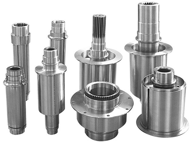
Custom Worm Wheel and Worm Gear Manufacturing Techniques
Engineering and supply chain guidance for global OEM and Tier 1 sourcing teams.
1. Executive Summary
Custom worm wheel and worm gear manufacturing is a fit-and-function discipline, not simply a gear-cutting operation. A worm, usually a hardened screw-like member, meshes with a bronze, steel, or engineered-material wheel on a crossed axis. The pair can deliver high reduction in a compact envelope, controlled motion, and, in selected geometries, resistance to back-driving. These benefits depend on exact tooth geometry, center distance, lubrication, heat dissipation, and matched surface finishes.
Unlike an off-the-shelf reducer, a custom pair must be designed as a matched system. Ratio, number of worm starts, module or diametral pitch, lead angle, pressure angle, handedness, center distance, backlash, face width, bore geometry, material, heat treatment, and lubricant all affect performance. A small error in lead or alignment can create edge contact, heat, noise, premature pitting, or unacceptable efficiency.
For global OEM and Tier 1 buyers, the commercial challenge extends beyond cutting teeth. The supplier must convert product requirements into a repeatable process, control material and heat treatment, document every critical dimension, and protect delivery across revisions and demand changes. IndustryApex Technology, operating through IndustryApex CNC, combines engineering, precision machining, inspection, and supply chain control for this purpose.
2. Technical Deep Dive
A worm drive transfers torque between typically nonparallel, often perpendicular, shafts. Its reduction ratio is broadly determined by the number of worm wheel teeth divided by the number of worm starts. Lead angle influences sliding velocity, efficiency, thrust loading, lubrication demand, and the possibility of back-driving. Self-locking should never be assumed from geometry alone; it must be validated against load, friction, vibration, lubrication, and safety requirements.
Define the gear pair before cutting
The engineering process begins with the operating envelope. The drawing or specification should identify module or diametral pitch, tooth count, number of starts, pressure angle, lead and helix direction, pitch diameters, center distance, face width, bore and keyway details, allowable backlash, runout, hardness, surface finish, and inspection standard. CAD tooth generation and contact analysis help predict interference, undercutting, contact ratio, and flank loading. Thermal calculations are also important because sliding friction can generate substantially more heat than a comparable spur gear set.
For custom applications, the wheel and worm should be reviewed together rather than as separate part numbers. The wheel may require a special hub, flange, spline, or bearing seat, while the worm may include journals, shoulders, threads, or an integrated shaft. Design-for-manufacturing review can preserve the required contact pattern while reducing setups, tool changes, and difficult inspection points.
Select materials for sliding wear and duty cycle
The conventional pairing is a hardened alloy-steel worm with a bronze wheel. Carburized, nitrided, or induction-hardened steels can provide a wear-resistant worm flank, while phosphor bronze or aluminum bronze offers compatible sliding behavior and helps protect the more expensive component. Steel-on-steel pairs may be appropriate for high-load or space-limited designs, but they demand careful surface treatment, lubrication, and thermal validation. Ductile iron, stainless steel, and engineered polymers can serve specialized environments when strength, corrosion resistance, weight, or noise is the priority.
Use the right process for geometry and volume
Manufacturing normally begins with turning the wheel blank, bore, hub, and reference faces, followed by preparation of the worm blank and shaft features. A dedicated hob matched to the worm’s module, lead, and pressure angle generates the wheel tooth form with high repeatability. Gear shaping, form milling, or controlled 3-5 axis machining can be effective for prototypes, low-volume programs, unusual clearances, or designs that do not justify dedicated tooling.
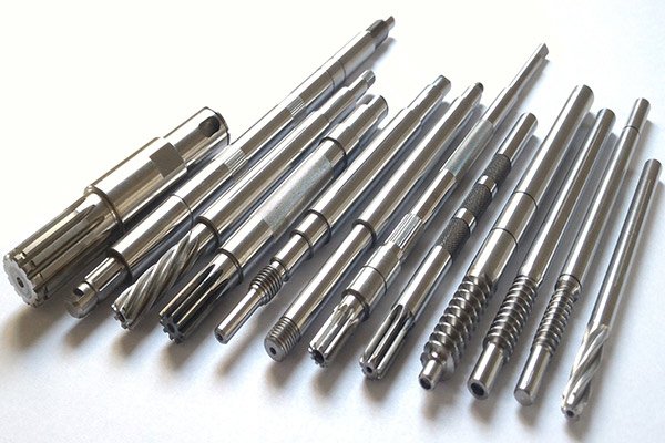
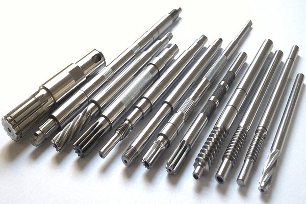
The worm thread can be produced by precision turning, thread milling, or form grinding, depending on material hardness, lead accuracy, and required surface finish. After heat treatment, precision grinding may be needed on the worm flanks, journals, faces, or wheel bore. Controlled lapping or paired running-in can improve contact conformity, but it must not mask an incorrect tooth form or excessive alignment error. Deburring is especially important at tooth edges, keyways, oil holes, and shaft transitions because loose burrs can damage seals and contaminate lubrication.
Control heat treatment, finishing, and inspection
Heat treatment should be selected around the load cycle and material pairing. Carburizing provides a hard case with a tough core; nitriding can limit distortion on suitable steels; and induction hardening can target defined load zones. Parts should be stress-relieved or stabilized when necessary before final grinding. The wheel material, hardness, and surface finish must remain compatible with the worm so that increased hardness does not simply accelerate wheel wear.
Inspection must evaluate both geometry and operating behavior. Typical controls include tooth profile and lead, pitch or cumulative pitch error, concentricity, axial and radial runout, tooth thickness, bore size, hardness, and flank roughness. A gear measuring machine or CMM verifies critical geometry, while a functional roll test checks mesh, torque, noise, and contact pattern. Engineers may use marking compound to confirm that load is distributed across the intended flank rather than concentrated at an edge. First-article reports, material certificates, heat-treatment records, and batch-level inspection data provide the traceability required for regulated or safety-critical programs.
3. The ODM & Supply Chain Advantage
Buying a custom gear pair creates more exposure than buying two machined parts. Geometry, material, heat treatment, tooling, inspection, assembly, packaging, and delivery all influence the customer’s final reducer or actuator. A fragmented supplier base can create unclear accountability, inconsistent revisions, and delays when a design change affects several processes.
IndustryApex Technology’s core identity is a supply chain integrator and ODM solution provider. The team can participate before production by reviewing application loads, proposing manufacturable wheel and worm architecture, confirming critical-to-function features, and helping the OEM convert performance targets into drawings, specifications, and inspection plans. This ODM approach is valuable when the customer needs a complete component solution rather than isolated machining capacity.
The manufacturing edge is a fully controlled precision manufacturing system with ERP and over 30 years of experience. ERP connects revision-controlled CAD data, bills of material, routings, material lots, work orders, inspection results, and shipment status. That visibility supports capacity planning, engineering-change control, lot traceability, and more reliable delivery commitments.
- Process integration: 3-5 axis CNC, EDM, precision grinding, and complementary finishing reduce handoffs between critical operations.
- Capability breadth: Industrial ceramics can support wear-resistant, insulating, or high-temperature adjacent components where a metallic gearset alone is insufficient.
- Quality control: First-article inspection, in-process verification, hardness testing, gear measurement, and final documentation can be aligned with the customer’s quality plan.
- Supply continuity: Approved material sources, controlled subcontractors, production scheduling, protective packaging, and demand visibility help reduce disruption and expedite risk.
This structure is designed for global OEM and Tier 1 suppliers that require one accountable manufacturing partner. It can reduce total landed cost by limiting duplicate inspection, engineering correspondence, freight movements, and corrective-action loops. It also makes it easier to scale from prototype quantities to repeat production without rebuilding the process at every stage.
4. Industry Applications
Worm drives are selected when compact reduction, controlled positioning, quiet operation, or high torque multiplication is more important than maximum mechanical efficiency. Application engineering must still verify duty cycle, thermal limits, lubrication, shock loading, and whether a separate brake is required. Typical uses include actuators, valve operators, indexing systems, conveyors, lifting mechanisms, and rotary adjustment assemblies.
| Sector | Typical requirement | Manufacturing response |
|---|---|---|
| Fluid power and pumps | Compact torque transmission, low backlash, contamination resistance | Hardened worm and compatible bronze wheel, controlled bores, sealing surfaces, and documented inspection for hydraulic pump parts. |
| Factory automation and conveyors | Repeatable positioning, long cycle life, low noise | Accurate lead control, matched sets, low runout, and functional roll testing. |
| Construction and agricultural machinery | Shock loads, dirt, temperature variation, and serviceability | Robust steel or ductile components, suitable hardening, generous fillets, and protected lubrication paths. |
| Packaging and process equipment | Washdown compatibility, clean operation, and precise indexing | Corrosion-resistant materials, controlled surface finish, food-compatible lubrication where specified, and sealed interfaces. |
| Medical and optical equipment | Low noise, smooth adjustment, compact packaging, and traceability | Fine backlash control, precision grinding, clean handling, and documentation aligned with medical component machining requirements. |
| Aerospace support and non-flight-critical mechanisms | Weight control, repeatability, material certification, and configuration control | Qualified processes, first-article documentation, controlled revisions, and support for aerospace CNC machining programs. |
Worm gears are also used in energy equipment, solar tracking, industrial valves, and specialized handling systems. In every sector, selecting the correct material pair and validating the complete assembly is more reliable than optimizing tooth hardness or dimensional tolerance in isolation.
5. Call to Action
A successful custom worm wheel and worm gear program begins with complete application data. Share the required ratio, tooth count, module or pitch, pressure angle, lead and hand, center distance, backlash, materials, hardness, lubrication, duty cycle, operating environment, annual volume, and inspection expectations. A 2D drawing, 3D model, sample part, or performance target can provide the starting point for an engineering review.
Contact IndustryApex Technology through Contact Us to discuss design-for-manufacturing, prototype builds, production tooling, quality documentation, and supply continuity. For a broader view of precision component capabilities, visit the IndustryApex CNC manufacturing platform.