
- Shaft
- Molds&Tools
- Hydraulics And Pump
- Hair transplant needle
- Hydraulics And Pump
- Precision CNC Shaft Machining Manufacturer for High Performance Applications
- Energy Industry CNC Machining Parts Supplier
- Aerospace Structural Components for OEM Programs
- Aerospace Structural Components for OEM Programs
- Automotive & EV CNC Machining Parts Supplier for OEM and Tier 1
- Medical Device CNC Machining Services
Long Shaft CNC Turning Tolerances: A Practical Design and Inspection Guide

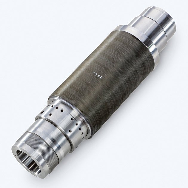
Long shaft CNC turning tolerances determine whether a machined component will meet functional requirements for concentricity, straightness and dimensional accuracy. Unlike compact turned parts, shafts with length-to-diameter ratios above 10:1 face amplified deflection, chatter and thermal drift that directly constrain achievable precision. This guide explains how geometry, material properties, process planning and inspection methods interact to define realistic tolerance expectations for procurement and design teams.
Key answer: Long shaft CNC turning tolerances typically range from ±0.05 mm for general features to ±0.01 mm for ground diameters, with concentricity held to 0.02–0.05 mm depending on L/D ratio, material stiffness, fixturing strategy and secondary operations. Achieving tighter limits requires steady rests, tailstock support, controlled cutting parameters, post-machining grinding and coordinate measurement to verify cylindricity and runout across the entire shaft length.
Why Long Shaft Geometry Drives Tolerance Limits
The length-to-diameter ratio is the primary geometric factor influencing long shaft CNC turning tolerances. As L/D increases, bending moments under cutting forces grow exponentially, causing mid-span deflection that manifests as diameter variation and taper.
- L/D 5–10: Standard turning practices with three-jaw chuck and tailstock support typically hold ±0.03–0.05 mm on diameter
- L/D 10–20: Steady rests become necessary; expect ±0.05–0.08 mm without secondary grinding
- L/D above 20: Multiple steady rests, reduced depth of cut and finish grinding required to maintain ±0.05 mm or better
Slender shafts also exhibit higher susceptibility to chatter, which creates periodic surface waves that violate both diameter and concentricity tolerances. Controlling spindle speed, tool geometry and engagement depth becomes critical as stiffness decreases.
Material Properties and Machinability Impact
Material selection directly affects both cutting behavior and dimensional stability during long shaft turning. High-strength alloys and hardened steels present greater challenges than softer materials.
Carbon and alloy steels (1045, 4140): Moderate machinability; post-heat-treat hardness above 35 HRC typically requires grinding to hold ±0.02 mm or tighter. Residual stresses from turning can cause distortion after release from fixturing.
Stainless steels (303, 316): Work hardening during cutting increases tool wear and deflection. Diameter tolerances of ±0.05 mm are realistic in the turned state; concentricity requires careful attention to tool sharpness and consistent engagement.
Aluminum alloys (6061, 7075): Lower cutting forces reduce deflection, enabling tighter as-turned tolerances (±0.025–0.05 mm). However, thermal expansion from cutting heat and low elastic modulus still limit straightness on very long shafts.
According to Protolabs guidance on CNC machining tolerances, material hardness and thermal properties influence both process capability and inspection repeatability.
Fixturing and Support Strategies
The lathe setup determines how effectively cutting forces are resisted and how much deflection occurs during material removal. Poor fixturing strategy is the most common cause of tolerance failures in long shaft production.
Standard Three-Jaw Chuck and Tailstock
Suitable for L/D up to approximately 10:1. The tailstock center provides axial support but does not prevent radial deflection at mid-span. Concentricity depends on chuck jaw condition and workholding pressure distribution.
Steady Rests
Adjustable steady rests contact the shaft at one or more intermediate points, converting a cantilevered beam into multiple supported spans. Proper placement reduces maximum deflection by 70–85%. However, steady rest jaws can leave witness marks or induce localized deformation if pressure is excessive or if the contact surface is not pre-machined to a reference diameter.
Between-Centers Turning
Both ends are supported by centers, and the workpiece is driven by a dog or faceplate. This method maximizes support but limits access to end features and requires careful alignment to avoid inducing runout.
Each additional support point introduces a new tolerance stack and potential misalignment. The setup must be qualified with a test bar or existing reference shaft before production begins.
Process Parameters That Affect Dimensional Control
Cutting speed, feed rate and depth of cut must be balanced against deflection, chatter and tool wear. For long shaft CNC turning tolerances below ±0.05 mm, process parameters typically follow these ranges:
| Operation | Depth of Cut (mm) | Feed Rate (mm/rev) | Expected Tolerance |
|---|---|---|---|
| Roughing | 2.0–4.0 | 0.2–0.4 | ±0.15–0.25 mm |
| Semi-finishing | 0.5–1.0 | 0.1–0.2 | ±0.05–0.10 mm |
| Finishing | 0.1–0.3 | 0.05–0.10 | ±0.025–0.05 mm |
Reduced engagement in finishing passes minimizes deflection but increases cycle time. Coolant flow and temperature control are essential to prevent thermal growth during extended machining operations.
Tool Geometry and Wear
Worn or improperly selected insert geometry increases cutting forces and generates inconsistent surface finish. Positive rake angles reduce force but may compromise edge strength in harder materials. Tool life monitoring and scheduled replacement prevent gradual tolerance drift across a production batch.
Secondary Operations and Final Tolerances
Many applications require shaft grinding or cylindrical grinding after turning to achieve diameter tolerances below ±0.02 mm and concentricity within 0.01 mm. Grinding removes the work-hardened surface layer, corrects minor taper and delivers superior surface finish.
Cylindrical grinding: Provides uniform diameter control and concentricity across the full length. Typical capability is ±0.005–0.01 mm with surface finish Ra 0.2–0.4 µm.
Centerless grinding: Suitable for shafts without critical features that require indexed positioning. Offers high throughput but less control over specific diameter zones.
Hard turning with CBN or ceramic tooling can approach ground-quality tolerances (±0.01–0.02 mm) in hardened steels, reducing process steps. However, this requires rigid machine tools and careful thermal management, making it practical primarily for moderate L/D ratios.
Inspection Methods and Verification Evidence
Measurement strategy must account for the full length of the shaft and detect localized deviations, not just endpoints. Standard inspection techniques include:
- Micrometer or caliper at multiple stations: Quick verification of diameter, but cannot detect taper or cylindricity errors
- Coordinate measuring machine (CMM): High-accuracy measurement of diameter, straightness and concentricity along the shaft axis. Requires proper support to avoid sag during measurement
- Bench centers with dial indicator: Practical shop-floor method to verify runout and concentricity. The shaft is rotated between centers while an indicator contacts the surface at multiple axial positions
- Cylindricity measurement: Dedicated systems capture full surface profile, identifying taper, ovality and lobing
As noted in Hubs’ ISO tolerance guidance, specifying measurement locations and datum references in engineering drawings prevents ambiguity and ensures consistent acceptance criteria.
Thermal stabilization is essential before measurement. Shafts removed from machining operations can exhibit dimensional variation of 0.01–0.02 mm until they reach ambient temperature.
Design Considerations for Tolerance Allocation
Designers should allocate tighter tolerances only where functionally necessary. Over-specifying precision on non-critical features increases cost without improving performance. Consider these design practices:
- Specify general tolerances per ISO 2768-m or equivalent for non-mating surfaces
- Call out tight diameter tolerances (±0.01–0.02 mm) only for bearing journals, seal surfaces and spline fits
- Use concentricity or runout callouts relative to a defined datum axis rather than individual diameter tolerances
- Include straightness tolerance when the shaft must pass through close-fitting guides or housings
- Allow for material removal in secondary operations by specifying pre-grind and post-grind dimensions where applicable
Procurement teams should review supplier process capability data for similar L/D ratios and materials. CNC shaft machining evaluation should include fixturing strategy, steady rest configuration, grinding capacity and CMM availability.

Practical Checklist for Long Shaft Tolerance Planning
- Calculate L/D ratio and confirm supplier has appropriate steady rest capacity for the shaft length
- Verify material machinability and whether post-heat-treat grinding is required
- Specify datum references for concentricity and straightness measurements
- Request process capability studies (Cpk data) for similar shaft geometries
- Confirm inspection equipment capability, including CMM bed length and straightness verification methods
- Review fixturing setup drawings or photos to understand support strategy
- Clarify whether tolerances apply to as-turned, pre-grind or final ground condition
- Establish thermal stabilization time before dimensional inspection
Frequently Asked Questions
What is the tightest diameter tolerance achievable on long shaft CNC turning without grinding?
With optimized fixturing, controlled cutting parameters and low L/D ratios (below 10:1), as-turned diameter tolerances of ±0.025–0.03 mm are achievable in stable materials like aluminum and free-machining steel. Higher L/D ratios or harder materials typically require ±0.05 mm or wider in the turned state, with grinding used to reach ±0.01–0.02 mm.
How does concentricity tolerance differ from diameter tolerance in shaft turning?
Diameter tolerance controls the size of a feature, while concentricity controls how closely a feature’s axis aligns with a datum axis. A shaft can meet diameter tolerance at each measurement location but still violate concentricity if those diameters are not coaxial. Concentricity is verified by measuring runout relative to a datum axis, typically using a CMM or bench centers with dial indicator.
When is a steady rest required for long shaft turning?
A steady rest is typically required when the L/D ratio exceeds 10:1 or when diameter tolerances below ±0.05 mm are specified on longer shafts. The steady rest reduces mid-span deflection and chatter, enabling controlled material removal. For very long shafts (L/D above 20:1), multiple steady rests may be necessary.
Can hard turning replace grinding for tight tolerances on long shafts?
Hard turning with CBN tooling can achieve ±0.01–0.02 mm diameter tolerance and Ra 0.4–0.8 µm surface finish on hardened steels, approaching ground quality. However, this requires extremely rigid machine tools and careful deflection control. For L/D ratios above 12:1 or tolerances below ±0.01 mm, cylindrical grinding remains the more reliable process.
How should I specify straightness tolerance on a long shaft drawing?
Straightness is specified as the maximum allowable deviation from a perfect straight line along the shaft axis, measured over the specified length. Use a straightness symbol with tolerance zone in the feature control frame, referencing the datum axis. Typical straightness tolerances for functional shafts range from 0.05–0.10 mm over length, verified by CMM or dial indicator on bench centers.
What measurement equipment is required to verify long shaft CNC turning tolerances?
Diameter and concentricity verification requires either a CMM with sufficient bed length and proper workpiece support, or bench centers with a dial indicator for runout measurement at multiple axial positions. Cylindricity measurement systems provide full surface profiling. Standard micrometers verify diameter but cannot detect taper or concentricity errors across the shaft length.
Conclusion
Long shaft CNC turning tolerances depend on a controlled interaction between geometry, material, fixturing and inspection. Shafts with higher L/D ratios require steady rests, reduced cutting forces and often secondary grinding to meet diameter tolerances below ±0.05 mm and concentricity within 0.02 mm. Designers should specify tight tolerances only where functionally necessary and ensure measurement methods can verify the full shaft profile. Procurement teams should evaluate supplier fixturing capability, process data for similar geometries and inspection equipment before committing to tolerance requirements. For precision shaft production with verified process control, submit your drawings for detailed feasibility review and capability assessment.