
- Shaft
- Molds&Tools
- Hydraulics And Pump
- Hair transplant needle
- Hydraulics And Pump
- Precision CNC Shaft Machining Manufacturer for High Performance Applications
- Energy Industry CNC Machining Parts Supplier
- Aerospace Structural Components for OEM Programs
- Aerospace Structural Components for OEM Programs
- Automotive & EV CNC Machining Parts Supplier for OEM and Tier 1
- Medical Device CNC Machining Services
CNC Turn Mill Machining Tolerances: A Practical Design and Inspection Guide

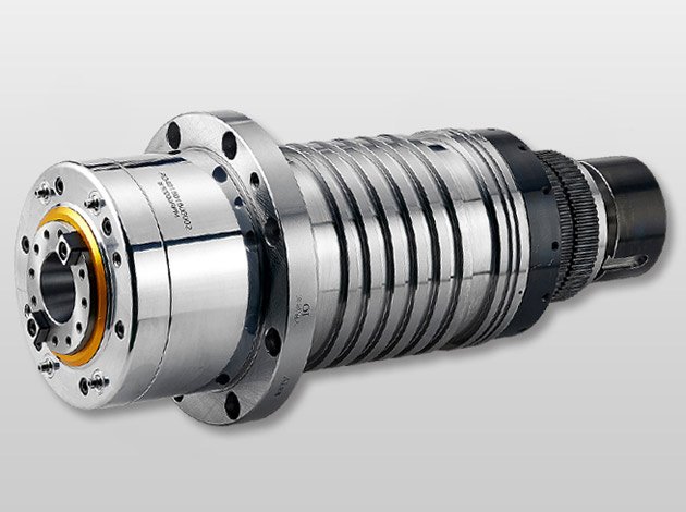
Achieving consistent dimensional accuracy in CNC turn mill machining tolerances depends on understanding how part geometry, material properties, thermal behavior and measurement strategy interact across a single-setup process. Unlike sequential turning and milling operations where intermediate inspection is possible, turn mill centers complete complex features—radial holes, off-axis milling, concentric bores—in one clamping, making tolerance stack-up prediction and in-process control critical for OEM procurement teams evaluating suppliers.
Key answer: CNC turn mill machining tolerances are governed by machine kinematics, thermal drift, workpiece material stability, tool deflection and the measurement method used for verification. Typical achievable tolerances range from ±0.01 mm for diameter and length dimensions to ±0.02 mm for position accuracy on features machined in a single setup, though specific results depend on part size, material hardness and geometric complexity.
Why CNC Turn Mill Machining Tolerances Differ from Standalone Processes
Turn mill machining combines rotary turning operations with indexed or simultaneous milling on a single platform. The absence of part transfer eliminates fixture repeatability error, but introduces new tolerance drivers:
- Thermal growth: Extended cycle times in one setup generate cumulative heat in the spindle, turret and workpiece
- Tool path switching: Transition between turning and milling modes requires accurate C-axis indexing and B-axis positioning
- Chip management: Accumulated chips can interfere with probing or affect coolant flow, impacting dimensional stability
- Clamping deformation: Thin-walled or cantilevered features may deflect under cutting forces when unsupported by tailstock
These factors mean that CNC turn mill machining tolerances must be verified not only by final inspection, but also through in-process probing and process capability studies that account for thermal cycles and tool wear progression.
Geometry-Specific Tolerance Considerations
Concentric Features and Radial Runout
Concentric bores, journals and seal surfaces benefit most from single-setup machining because all diameters share a common datum established at initial clamping. Radial runout between features typically remains below 0.005 mm when both are machined without re-chucking. However, длина cantilevered sections increases deflection, and features more than five diameters from the chuck face may require tailstock support or reduced depth of cut to maintain concentricity.
Cross Drilled and Radial Holes
Radial holes drilled or milled into rotating shafts must maintain positional tolerance relative to the turned OD and often to angular clocking. Cross drilled turned parts tolerances are affected by C-axis repeatability (typically ±0.01° on modern machines), drill wander in interrupted cuts, and coolant pressure that can deflect thin walls. Positional tolerance of ±0.02 mm is achievable for holes up to 10 mm diameter in stable materials like aluminum and low-carbon steel, but may open to ±0.05 mm in work-hardening stainless alloys or when drilling through curved surfaces.
Off-Center Milled Features
Flats, keyways, and pockets milled onto turned diameters introduce asymmetric cutting forces. The resulting deflection depends on part rigidity, tool engagement and whether the feature is milled with the part rotating (mill-turn mode) or indexed stationary. Flatness and parallelism tolerances of ±0.02 mm are standard for features up to 50 mm length on steel shafts with diameter-to-length ratios above 1:3.
Material Influence on Achievable CNC Turn Mill Machining Tolerances
Material machinability, thermal expansion coefficient and work-hardening behavior directly affect tolerance capability:
| Material Group | Thermal Expansion (μm/m·°C) | Typical Diameter Tolerance (mm) | Key Challenge |
|---|---|---|---|
| Aluminum alloys (6061, 7075) | 23 | ±0.01 | Low stiffness, heat buildup |
| Carbon steel (1045, 4140) | 11 | ±0.01 | Moderate, stable machining |
| Stainless (303, 316) | 17 | ±0.015 | Work hardening, tool wear |
| Titanium (Ti-6Al-4V) | 9 | ±0.015 | Low thermal conductivity, spring-back |
| Inconel (718, 625) | 13 | ±0.02 | Extreme tool wear, heat retention |
High thermal expansion materials require controlled coolant temperature and post-machining stabilization time before final measurement. Aerospace CNC machining of titanium components often includes thermal soak periods and temperature-compensated inspection protocols to ensure dimensional conformance.

Process Control and Inspection Strategy
In-Process Probing
Modern turn mill centers support touch probes for mid-cycle measurement of critical dimensions. Probing after rough turning and before finish milling allows adaptive offsets to compensate for material variation or thermal drift. Probe repeatability is typically ±0.002 mm, but probing through coolant or chips degrades accuracy.
Post-Process Verification
Final inspection should match the functional tolerance type:
- Diameter and length: Micrometer or calibrated caliper, repeatability ±0.001 mm
- Concentricity and runout: Indicator on precision centers or CMM with rotary table
- Positional tolerance: CMM with GD&T evaluation software, capable of datum reference frame setup
- Surface finish: Contact or optical profilometer; Ra values below 0.8 μm require finish passes with worn or honed inserts
Inspection environment temperature must be controlled to 20 ±2 °C for precision work. Parts machined in one setup turn mill operations should stabilize thermally for at least one hour per 25 mm of cross-section before measurement.
Process Capability and SPC
Suppliers should demonstrate Cpk ≥1.33 for critical tolerances through at least 30-piece sample runs. Control charts tracking key dimensions across production lots reveal tool wear trends, thermal drift patterns and fixture degradation, allowing proactive adjustment before nonconformance occurs.
Design for Tolerance: Pre-Production Checklist
OEM engineering teams can reduce tolerance risk and supplier variability by validating these factors before releasing drawings:
- Specify geometric tolerances (GD&T) rather than bilateral coordinate dimensions wherever function allows; position, profile and runout callouts align naturally with turn mill capabilities
- Avoid tolerance stack-ups that require holding dimensions across datum changes; keep critical features referenced to a single primary datum established at clamping
- Confirm that positional tolerances on radial holes account for C-axis repeatability and drill wander; consult supplier capability data
- Review thermal expansion impact for materials with coefficients above 15 μm/m·°C; specify measurement temperature or add thermal soak requirements
- Request first-article inspection reports with full CMM data, including datum setup and measurement uncertainty statements
- For high-volume production, require process capability studies (Ppk, Cpk) documented over at least 100 consecutive parts
When to Tighten or Relax CNC Turn Mill Machining Tolerances
Tighter tolerances increase cycle time, tool cost and scrap risk. Functional analysis should guide specification:
- Tighten (±0.005 to ±0.01 mm) for bearing journals, seal surfaces, precision gears and mating splines where clearance or interference fit is critical
- Standard (±0.01 to ±0.02 mm) for general mechanical assemblies, robotic actuator housings and robotics components with clearance fits
- Relax (±0.05 to ±0.1 mm) for non-functional features, cosmetic surfaces, and features far from assembly interfaces
Unnecessary tight tolerances on non-critical features force suppliers to implement secondary operations or 100% inspection, increasing cost without functional benefit. Selective tolerance application—tight only where needed—optimizes both quality and economy.
Frequently Asked Questions
What tolerance can I expect for concentricity between two turned diameters on a turn mill center?
Concentricity between diameters machined in a single setup typically ranges from 0.005 to 0.01 mm, depending on part length, diameter ratio and material stability. This assumes both features are machined without re-chucking and that the part is supported adequately to prevent deflection. Runout improves when the longer diameter is machined first, allowing the shorter feature to be finish-turned with minimal remaining material to distort.
How does material hardness affect achievable CNC turn mill machining tolerances?
Harder materials increase tool wear rate, which causes gradual dimensional drift within a production batch. Materials above 35 HRC may require more frequent tool changes or adaptive offsets to maintain ±0.01 mm tolerances. Hard materials also exhibit greater spring-back after cutting, meaning finish passes must be lighter to avoid elastic recovery that opens tolerances. Conversely, softer materials like aluminum allow tighter tolerances but are more prone to burr formation and smearing.
Can I hold positional tolerance of ±0.01 mm on radial holes in a rotating shaft?
Positional tolerance of ±0.01 mm is achievable on radial holes up to 8 mm diameter in stable materials when using rigid toolholders, controlled feed rates and C-axis machines with ±0.005° repeatability. Holes larger than 10 mm or those crossing curved surfaces may require ±0.02 mm positional tolerance due to drill wander. Cross drilled parts quality control protocols including hole position probing and post-drill reaming can tighten results, but add cycle time.
Should I specify tolerances at 20 °C for precision turn mill parts?
Yes. High-precision components with tolerances below ±0.02 mm should include a note specifying measurement at 20 ±2 °C per ISO 1 standards. Materials with thermal expansion coefficients above 12 μm/m·°C can exhibit dimensional changes exceeding tolerance bands when measured at shop-floor temperatures varying from 15 to 30 °C. Specify thermal stabilization time and measurement temperature on drawings to avoid acceptance disputes.
What is the difference between standard and precision-grade turn mill machining tolerance capability?
Standard turn mill machining typically holds ±0.02 mm on diameters and ±0.05 mm on milled feature positions, suitable for most mechanical assemblies. Precision-grade work, required for medical CNC machining and aerospace components, targets ±0.005 to ±0.01 mm through climate-controlled machining environments, in-process probing, tool presetters and calibrated inspection equipment. The cost differential can reach 40-70% due to longer cycle times and higher scrap risk.
How do I verify that a supplier can consistently meet tight CNC turn mill machining tolerances?
Request process capability studies (Cpk reports) demonstrating at least 1.33 for critical dimensions over a minimum 30-piece sample. Review first-article inspection reports with full CMM data including measurement uncertainty statements. Ask for evidence of climate-controlled inspection facilities, calibrated tooling and ERP-tracked tool life management. Supplier facilities with ISO 9001 or AS9100 certification and documented SPC programs offer greater confidence in sustained tolerance performance across production volumes.
Conclusion
Successful specification and procurement of parts requiring tight CNC turn mill machining tolerances depends on aligning design intent with process capability, material behavior and inspection methodology. Single-setup machining eliminates fixture error but introduces thermal, deflection and tool wear variables that must be controlled through in-process probing, adaptive offsets and environmental management. OEM engineering teams should apply GD&T principles, specify measurement conditions, and validate supplier capability through documented process studies before committing to production volumes. For tolerance-critical components requiring validated manufacturing control, upload your drawings for a detailed capability assessment and quotation within 24 hours.
Sources
- Protolabs, Fine-Tuning Tolerances for CNC Machined Parts, https://www.protolabs.com/resources/design-tips/fine-tuning-tolerances-for-cnc-machined-parts/
- Hirsh Precision Products, What is CNC Machining?, https://hppi.com/knowledge-base/cnc-machining