
- Shaft
- Molds&Tools
- Hydraulics And Pump
- Hair transplant needle
- Hydraulics And Pump
- Precision CNC Shaft Machining Manufacturer for High Performance Applications
- Energy Industry CNC Machining Parts Supplier
- Aerospace Structural Components for OEM Programs
- Aerospace Structural Components for OEM Programs
- Automotive & EV CNC Machining Parts Supplier for OEM and Tier 1
- Medical Device CNC Machining Services
DFM for One Setup Turn Mill Machining: Reducing Risk Before Production

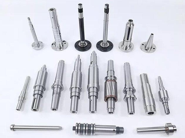
When a part requires both rotational and prismatic features—turned diameters, cross-drilled holes, milled flats, threaded bores—one setup turn mill machining eliminates multiple setups and the cumulative positioning error they introduce. But realizing that advantage depends on design choices made long before the first chip flies. Poor feature placement, unrealistic tolerances, or inaccessible inspection points can turn a theoretically ideal process into a costly rework cycle.
Key answer: DFM for one setup turn mill machining focuses on feature accessibility, tool clearance, datum strategy, and inspection feasibility within a single workholding setup. Early collaboration between design and manufacturing teams identifies geometric conflicts, optimizes feature sequences, and ensures that concentric, cross-drilled, and milled features can be produced and verified without repositioning the workpiece, reducing scrap risk and improving batch consistency.
Why One Setup Turn Mill Machining Demands Upstream DFM
Turn mill centers combine a live spindle, powered tooling, and C-axis or Y-axis interpolation, enabling complex geometries in one chucking. The promise is tighter tolerances, shorter cycle times, and elimination of datum shift. But that promise breaks down when designers specify features that conflict with tooling access, exceed machine kinematics, or cannot be inspected in situ.
Common failure modes include:
- Cross-drilled holes positioned too close to shoulders, blocking drill entry
- Concentric bores with tight positional tolerances that require multiple tool changes and thermal drift compensation
- Milled pockets or flats that demand tool extensions beyond rigidity limits
- Threaded features with no chamfer relief, causing tap breakage
- Inspection features accessible only after part removal, negating setup reduction
Addressing these issues during design review—not during first-article machining—is the essence of precision manufacturing system integration.
Feature Accessibility and Tool Clearance
Turn mill tooling must approach the workpiece from constrained angles. A cross-drilled radial hole intersecting a turned diameter is straightforward if the hole axis is perpendicular to the spindle centerline and no shoulders obstruct the drill. Add a 2 mm fillet at the shoulder, or position the hole 3 mm from a flange, and suddenly the drill requires a custom stub length or an angled approach that the machine cannot execute.
Design guidelines from CNC machining DFM literature recommend minimum clearances: 3× tool diameter from obstructions for standard tooling, 5 mm minimum depth for threaded holes to allow tap runout, and chamfers or undercuts at all thread exits. For mill turn work, add rotational constraints—ensure milled features do not require tool extensions that exceed 4× diameter, and verify that live-tool spindle orientation does not collide with the chuck or tailstock.
Datum Strategy and Concentric Feature Control
One setup mill turn relies on a primary datum—typically the turned OD or a face—that remains constant throughout all operations. Concentricity, perpendicularity, and positional tolerances reference this datum. If the design specifies a secondary datum that cannot be established until after the part is flipped or re-chucked, the single-setup advantage evaporates.
Best practice: define the primary datum as the first turned feature, ensure all subsequent features—cross-drilled holes, flats, bores—reference that datum, and avoid callouts that require CMM verification of internal features inaccessible to in-process probing.
Tolerance Allocation and Process Capability
Turn mill machines deliver positional accuracy in the range of ±0.01 to ±0.02 mm under stable thermal conditions. Concentricity between turned and milled features typically holds to 0.02 mm TIR when executed in one setup. Specifying tighter tolerances—0.005 mm positional tolerance on a cross-drilled hole, for example—may exceed process capability without secondary grinding or honing, negating the cost advantage.
Tolerance stack-up is less forgiving in one setup work because every feature shares a single datum. A 0.01 mm runout on the turned OD propagates to every milled flat and drilled hole. Design reviews should verify that tolerance chains account for tool deflection, thermal growth, and machine repeatability, and that GD&T callouts align with the capabilities documented in supplier process capability studies.
| Design Element | Recommended Practice | Risk if Ignored |
|---|---|---|
| Cross-drilled hole position | ≥5 mm from shoulders, chamfered entry | Drill breakage, positional error |
| Concentric bore tolerance | ±0.02 mm TIR, single-point boring bar | Exceeded capability, rework |
| Milled pocket depth | ≤3× tool diameter unsupported length | Chatter, poor surface finish |
| Thread relief | 1× pitch undercut or chamfer | Tap breakage, incomplete thread |
| Inspection access | Features probeable in-machine | Delayed feedback, scrap in batch |
Inspection Planning Within the Setup
One of the most overlooked DFM considerations is whether critical features can be verified before the part leaves the machine. In-process probing of turned diameters, hole positions, and face runout provides immediate feedback and enables real-time offsets. But if a design specifies a concentricity callout between an internal bore and an external diameter, and the bore is inaccessible to the machine probe, the operator has no feedback until CMM inspection hours or days later.
Effective DFM for one setup turn mill machining includes:
- Probe-accessible critical features: diameters, hole positions, face perpendicularity
- Geometric tolerances that can be verified with on-machine measurement (runout, positional tolerance) rather than requiring offline CMM
- Datum features that remain exposed and measurable throughout the operation sequence
For parts destined for aerospace applications or medical device manufacturing, inspection evidence is non-negotiable. Designing for in-process verification reduces cycle time and documentary burden.
Material Selection and Workholding Considerations
Turn mill machines grip the workpiece in a chuck or collet throughout the entire operation. Materials with poor machinability—high work-hardening alloys, brittle ceramics—introduce cutting forces that can shift the part or deform thin walls. If the design includes thin-walled sections, deep pockets, or cantilevered features, DFM review must confirm that workholding can maintain position under milling loads without distortion.
For example, a titanium precision shaft with cross-drilled oil passages and milled keyways benefits from one setup mill turn, but only if the wall thickness around the keyway exceeds 2 mm and the cross-drilled holes are positioned away from high-stress areas that could deflect under clamping force.
Practical DFM Checklist for Turn Mill Parts
- All critical features reference a single primary datum established in the first turning operation
- Cross-drilled holes positioned ≥5 mm from shoulders, with chamfered entries
- Concentric tolerances within ±0.02 mm TIR capability range
- Milled features accessible with standard tooling (≤4× diameter overhang)
- Threaded holes include relief undercuts or chamfers at thread exit
- Critical dimensions measurable with on-machine probing
- Wall thickness ≥2 mm in milled or drilled areas to resist deflection
- Material machinability compatible with continuous chucking and live tooling

Scaling from Prototype to Production
A design that machines successfully as a prototype may fail in production if it relies on manual offsets, operator judgment, or post-process rework. One setup turn mill machining scales efficiently only when the process is fully defined—toolpaths proven, inspection sequences automated, and tolerance capability validated across multiple lots.
OEM teams evaluating suppliers for mill turn complex parts should request first-article inspection reports, process capability studies (Cpk data for critical features), and evidence of in-process control. A supplier’s ability to maintain concentric and positional tolerances across a 500-piece batch, without manual touch-up, is the clearest indicator of DFM maturity.
Conclusion
DFM for one setup turn mill machining is not a checklist applied after design freeze—it is a collaborative discipline that shapes geometry, tolerances, and inspection strategy from the first CAD session. When design teams account for tool access, datum continuity, and in-process verification early, they unlock the full cost and quality advantages of single-setup manufacturing. For complex parts requiring both turned and milled features, that upstream investment is the difference between a streamlined production process and a cycle of rework and scrap.
If your next project includes concentric bores, cross-drilled passages, or tight positional tolerances in a rotational component, upload your drawings for a manufacturability review and detailed quote.
Frequently Asked Questions
What is the main advantage of one setup turn mill machining?
One setup turn mill machining eliminates workpiece repositioning, reducing cumulative positional error and improving concentricity between turned and milled features. It shortens cycle time, lowers labor cost, and simplifies quality control by maintaining a single datum reference throughout all operations. However, these benefits depend on designs that accommodate tool access and in-process inspection within the setup.
How tight can positional tolerances be in one setup mill turn work?
Most turn mill machines maintain positional accuracy of ±0.01 to ±0.02 mm under stable conditions. Tighter tolerances may require secondary operations or exceed standard process capability. Design reviews should compare specified tolerances against supplier Cpk data for turned diameters, cross-drilled holes, and milled features to ensure the design is within normal capability limits without costly process adjustments.
Can all materials be machined in one setup on a turn mill center?
Materials with good machinability—aluminum, steel, stainless steel, titanium—are well suited to one setup turn mill work. Materials that work-harden rapidly, have low thermal conductivity, or are brittle require careful DFM review to ensure that cutting forces and heat do not cause workpiece distortion or chucking slippage. Thin-walled or cantilevered features in difficult materials may need workholding modifications or intermediate stress-relief steps.
What design features most often cause turn mill setup failures?
Common issues include cross-drilled holes too close to shoulders, milled pockets requiring excessive tool overhang, threaded holes without thread relief, and tolerance callouts that reference inaccessible or unmeasurable datums. Features that cannot be inspected in-process delay feedback and increase scrap risk. Early DFM review identifies these conflicts before tooling and programming begin.
How do I verify a supplier’s capability for one setup turn mill parts?
Request first-article inspection reports showing actual measurements against GD&T callouts, process capability studies (Cpk ≥1.33 for critical features), and evidence of in-process control such as probe data logs. Ask whether critical features are verified on-machine or require offline CMM, and review the supplier’s workholding and fixturing strategy for thin-walled or complex geometries. Suppliers with mature systems provide this documentation as standard practice.
Should I design for one setup turn mill or multi-setup machining?
Choose one setup turn mill machining when the part has both rotational and prismatic features, tight concentric or positional tolerances between those features, and production volumes that justify the programming and tooling investment. Multi-setup machining may be more economical for very large parts, geometries that exceed turn mill work envelope, or low-volume prototypes where setup time is less critical than machine availability. A DFM review comparing both approaches clarifies the trade-offs for each specific part geometry and tolerance requirement.