
- Shaft
- Molds&Tools
- Hydraulics And Pump
- Hair transplant needle
- Hydraulics And Pump
- Precision CNC Shaft Machining Manufacturer for High Performance Applications
- Energy Industry CNC Machining Parts Supplier
- Aerospace Structural Components for OEM Programs
- Aerospace Structural Components for OEM Programs
- Automotive & EV CNC Machining Parts Supplier for OEM and Tier 1
- Medical Device CNC Machining Services
Complex Pocket CNC Milling Tolerances: A Practical Design and Inspection Guide

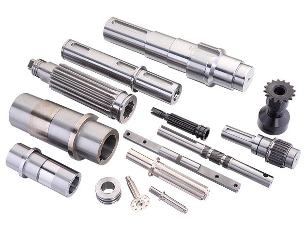
Complex pocket CNC milling tolerances depend on feature geometry, material response, tooling strategy, and inspection method. Unlike simple through-features, pockets introduce limited tool access, corner radius constraints, thermal buildup, and multi-axis programming complexity that directly affect dimensional stability. Understanding these interdependencies helps engineering teams specify achievable tolerances, reduce rework cycles, and accelerate supplier qualification.
Key answer: Complex pocket CNC milling tolerances typically range from ±0.05 mm for general features to ±0.01 mm for critical dimensions in controlled setups. Achievable results depend on pocket depth-to-width ratio, corner radii, material thermal behavior, tooling rigidity, and whether measurement occurs in-process or post-machining. Tighter specifications require secondary operations, fixture stability upgrades, or multi-axis coordination validated through capability studies.
How Pocket Geometry Affects Achievable Tolerances
Pocket geometry introduces mechanical and thermal constraints absent in open milling. Deep pockets restrict coolant flow, extend tool overhang, and limit chip evacuation, all of which reduce dimensional stability. According to Five Flute’s manufacturing principles analysis, depth-to-diameter ratios above 3:1 amplify deflection-induced error, particularly in aluminum and softer alloys where cutting forces generate elastic deformation.
Corner radii directly control tool selection and load distribution. Sharp internal corners require smaller endmills with reduced stiffness, while larger radii permit robust tooling and lower vibration. For multi-axis CNC solutions targeting ±0.02 mm positional tolerance, corner radii should match or exceed tool diameter to avoid chatter and premature wear.
Wall thickness between adjacent pockets affects rigidity during cutting. Thin walls deflect under lateral forces, creating dimensional variation even with stable spindle control. Design walls to at least 2.5× the tolerance band; for example, a ±0.03 mm tolerance requires minimum 0.15 mm clearance from nominal to prevent elastic distortion during final passes.
Depth-to-Width Ratio and Tool Deflection
As pocket depth increases relative to opening width, tool overhang grows and bending stiffness falls. A 10 mm deep pocket milled with a 6 mm diameter tool experiences measurably higher deflection than a 5 mm deep feature using the same cutter. This deflection translates to tapered walls, out-of-tolerance floor flatness, and inconsistent corner geometry.
Mitigation strategies include stepped roughing to reduce final-pass forces, adaptive feed rates tied to engagement angle, and tooling with enhanced stiffness-to-reach ratios such as carbide with extended neck designs.
Material-Specific Tolerance Considerations for Complex Pockets
Material behavior during complex pocket CNC milling directly governs dimensional outcomes. Aluminum alloys expand and contract with heat faster than steel, making thermal management critical for tolerance control. The ISO 2768-1 tolerance framework provides baseline expectations, but pocket machining in aluminum often requires tighter process control to achieve even medium-grade tolerances due to coefficient of thermal expansion effects.
Steel and titanium maintain better dimensional stability under heat but generate higher cutting forces, amplifying tool deflection in deep pockets. Titanium’s work-hardening tendency and low thermal conductivity concentrate heat at the tool-workpiece interface, accelerating wear and introducing gradual dimensional drift across production batches.
Aluminum Pocket Milling Tolerances
6061-T6 and 7075-T6 aluminum are widely specified for pocketed components in aerospace and robotics. Both alloys machine cleanly but require flood coolant and controlled feed rates to prevent built-up edge formation. Typical achievable tolerances for pockets deeper than 20 mm:
- General dimensions: ±0.05 mm to ±0.08 mm
- Critical functional surfaces: ±0.02 mm to ±0.03 mm with temperature-controlled environment
- Flatness of pocket floor: 0.03 mm to 0.05 mm over 100 mm span
For applications requiring aluminum CNC milling quality control protocols, post-machining stress relief and temperature stabilization before final inspection reduce rejection rates.
Steel and Titanium in Pocketed Geometries
4140 steel and Ti-6Al-4V introduce higher tool loads but reward careful programming with stable dimensional output. Pockets in these materials benefit from helical interpolation entry, optimized radial engagement, and ceramic or coated carbide tooling. Tolerance expectations shift based on heat treatment state; annealed materials permit tighter control than fully hardened conditions.
Process Variables That Define Tolerance Capability
Tolerance achievement in complex pocket CNC milling depends on coordinated control of spindle speed, feed rate, toolpath strategy, fixturing, and thermal management. Each variable interacts; optimizing one without addressing others yields marginal improvement.
| Process Variable | Impact on Tolerance | Control Strategy |
|---|---|---|
| Spindle Speed | Affects heat generation and surface finish | Match material-specific cutting speed; use high-speed spindles for aluminum |
| Feed Rate | Controls chip load and tool deflection | Adaptive feeds in corners; constant engagement toolpaths |
| Toolpath Strategy | Determines wall straightness and corner accuracy | Trochoidal or high-efficiency milling for deep pockets |
| Fixturing | Prevents workpiece movement under cutting forces | Multi-point clamping away from pocket zones; fixture plate design |
| Thermal Control | Minimizes expansion-induced dimension shift | Flood coolant, oil mist, or cryogenic delivery; soak time before measurement |
Three-axis milling of complex pockets often requires multiple setups, each introducing datum shift risk. Fully controlled precision manufacturing systems using tombstone fixtures or pallet changers maintain positional reference across operations, reducing cumulative tolerance stackup.
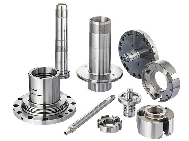
Inspection Methods and Measurement Uncertainty
Measurement approach affects reported tolerance conformance. Contact probing on a CMM captures pocket dimensions under near-zero thermal load, while in-process probing reflects real machining conditions but introduces probe wear and calibration drift.
For pockets with depth exceeding 30 mm, probe length and stylus configuration limit access to certain features. Articulating probe heads or geometric dimensioning and tolerancing (GD&T) inspection plans that prioritize functional datums over complete feature mapping improve efficiency without sacrificing acceptance confidence.
CMM vs. In-Process Probing
Coordinate measuring machines provide micron-level resolution but require temperature-stabilized environments (20°C ±1°C) and extended setup time. In-process probing offers immediate feedback for adaptive offsets but typically resolves to ±0.005 mm at best, limiting its utility for features tighter than ±0.02 mm.
Combining both methods—in-process verification for rough and semi-finish passes, followed by post-machining CMM validation—balances cycle time with dimensional assurance. This hybrid approach is standard in aerospace CNC machining where pocketed structural components demand both production efficiency and traceability.
Design Checklist for Specifying Complex Pocket Tolerances
Before releasing drawings, verify that tolerance callouts align with manufacturing capability and inspection feasibility:
- Limit depth-to-width ratio to 4:1 unless secondary operations are planned
- Specify corner radii equal to or greater than tool diameter for tolerance zones tighter than ±0.03 mm
- Call out critical dimensions using GD&T position or profile tolerance rather than bilateral limits
- Indicate primary datum features accessible for fixturing without interfering with pocket geometry
- Provide material specification including heat treatment state and expected hardness range
- Note whether dimensions apply at 20°C or as-machined condition
- Request capability study data (Cpk ≥1.33) for tolerances tighter than ±0.025 mm
For complex assemblies requiring design for manufacturability review, early supplier involvement identifies tolerance relaxation opportunities that preserve function while improving yield.
Frequently Asked Questions
What tolerance can I expect for a 25 mm deep pocket in 6061 aluminum?
For general features in 6061-T6 aluminum with standard 3-axis milling, expect ±0.05 mm to ±0.08 mm on lateral dimensions and 0.03 mm flatness on the pocket floor. Tighter tolerances (±0.02 mm) require temperature-controlled machining, high-stiffness tooling, and post-machining stress relief. Always specify inspection temperature and request process capability data for critical dimensions.
How does corner radius affect pocket milling tolerances?
Smaller corner radii require smaller diameter endmills, which deflect more under cutting loads and reduce dimensional stability. A 2 mm radius corner permits a robust 4 mm tool, while a 0.5 mm radius demands a 1 mm tool with significantly lower stiffness. For tolerances tighter than ±0.03 mm, match corner radius to tool diameter or larger to minimize deflection and chatter-induced error.
Should I specify in-process or post-machining inspection for tight pocket tolerances?
Use in-process probing for adaptive control during roughing and semi-finishing, then validate final dimensions with CMM inspection after thermal stabilization. In-process probing resolves to approximately ±0.005 mm and cannot replace CMM verification for tolerances below ±0.02 mm, but it reduces scrap by catching errors before final passes. Hybrid inspection protocols balance cycle time with measurement certainty.
Can ISO 2768 medium grade cover complex pocket features?
ISO 2768-m provides ±0.1 mm to ±0.3 mm depending on nominal size and is often adequate for non-critical pockets in commercial applications. However, deep pockets, thin walls, or features affecting assembly fits typically require explicit callouts tighter than medium grade. For functional surfaces, specify GD&T position or profile tolerances instead of relying on general tolerance notes.
How do I account for material thermal expansion in pocket tolerance specifications?
Specify inspection temperature (typically 20°C per ISO 1) and allow thermal soak time after machining before measurement. Aluminum expands approximately 23 µm/m/°C; a 100 mm pocket dimension can shift ±0.023 mm with a 10°C temperature difference. For assemblies with tight clearances, coordinate manufacturing and inspection environments or apply calculated thermal compensation factors agreed upon during design review.
What process capability should I require for ±0.02 mm pocket tolerances?
Request Cpk ≥1.33 for critical dimensions, which implies the process center lies within the tolerance zone and natural variation consumes no more than 75% of tolerance width. For ±0.02 mm specifications, this requires process standard deviation ≤0.005 mm. Capability studies should include at least 30 sequential parts measured under consistent conditions, with data stratified by operator, setup, and tool life stage.
Conclusion
Complex pocket CNC milling tolerances result from disciplined control of geometry, material behavior, cutting strategy, and inspection method. By understanding how depth ratios, corner radii, thermal expansion, and measurement uncertainty interact, engineering teams can specify achievable tolerances that balance functional requirements with manufacturing economics. Early collaboration with suppliers experienced in precision component production reduces revision cycles and accelerates qualification. Evidence-based tolerance decisions, supported by capability data and GD&T clarity, ensure consistent outcomes from prototype through volume production.