
- Shaft
- Molds&Tools
- Hydraulics And Pump
- Hair transplant needle
- Hydraulics And Pump
- Precision CNC Shaft Machining Manufacturer for High Performance Applications
- Energy Industry CNC Machining Parts Supplier
- Aerospace Structural Components for OEM Programs
- Aerospace Structural Components for OEM Programs
- Automotive & EV CNC Machining Parts Supplier for OEM and Tier 1
- Medical Device CNC Machining Services
Surface Grinding Tolerances: A Practical Design and Inspection Guide

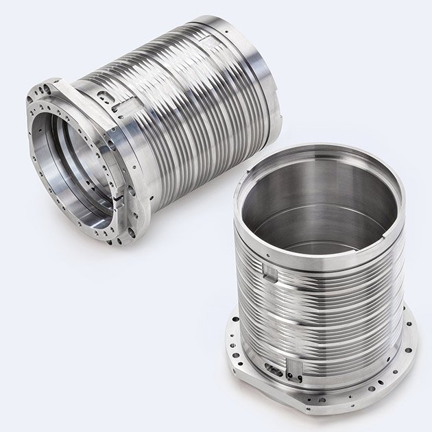
Surface grinding tolerances determine whether a valve flange seals under pressure, a bearing housing runs true for years, or a gage block maintains calibration. Achievable tolerances—typically ±0.0002″ to ±0.001″ for flatness and parallelism—depend on part geometry, material properties, grinding wheel specification, thermal stability, and measurement capability. Understanding these interdependencies helps procurement and engineering teams specify realistic requirements and select capable suppliers for precision grinding applications.
Key answer: Surface grinding tolerances of ±0.0002″ to ±0.0005″ are standard for precision work on stable materials with proper fixturing and thermal control. Tighter tolerances to ±0.0001″ require magnetic chucks, sub-spindle grinders, temperature-controlled environments, and coordinate measuring machines. Achievable results depend on part size, material hardness, required surface finish, wheel dress interval, and inspection method. Specify tolerances matched to functional requirements rather than theoretical limits.
How Geometry and Size Affect Surface Grinding Tolerances
Part size directly impacts achievable flatness. Small workpieces under 100 mm benefit from uniform magnetic chuck holding force and consistent wheel contact, enabling tolerances to ±0.0001″. Larger surfaces above 500 mm experience greater thermal gradients, deflection under grinding forces, and wheel wear across the traverse, making ±0.0005″ more realistic without intermediate dressing cycles.
Flatness tolerance must account for geometry:
- Solid blocks: High stiffness supports ±0.0002″ flatness over areas to 300 mm with reciprocating table grinders
- Thin plates: Deflection during grinding requires careful work-holding; expect ±0.0005″ to ±0.001″ without stress-relief cycles
- Pocketed housings: Non-uniform stiffness creates localized errors; rotary grinders with segmented chucks improve results
- Long rails: Thermal expansion over length limits practical tolerance to ±0.0003″ per 500 mm without temperature control
Parallelism between two ground surfaces depends on fixturing accuracy and reference surface condition. Magnetic chuck flatness, typically ±0.0001″ over 300 mm, sets the baseline. Grinding both surfaces in one setup preserves parallelism better than repositioning between operations.
Material Properties That Control Achievable Tolerances
Material hardness, thermal conductivity, and microstructure stability determine grinding behavior and tolerance capability. Hardened tool steels (58-62 HRC) grind predictably with aluminum oxide or CBN wheels, supporting ±0.0002″ tolerances when thermal damage is avoided. Softer materials below 30 HRC load the wheel quickly, degrading surface finish and geometric accuracy unless frequent dressing is applied.
Thermal expansion coefficients matter during grinding and measurement. Aluminum expands roughly three times more than steel per degree Celsius, making temperature-controlled grinding essential for tolerances tighter than ±0.0005″. Ceramics and carbides offer superior dimensional stability but require diamond wheels and rigid setups to prevent chipping.
According to HFW Industries, precision grinding services hold tolerances as tight as ±0.0002″ when material properties, geometry, and process parameters are properly matched. Residual stress from prior heat treatment or machining can cause post-grind distortion, particularly in carburized or nitrided components. Stress-relief grinding with reduced infeed rates and intermediate inspection helps maintain dimensional control.
Process Variables That Define Surface Grinding Tolerances
Grinding wheel specification—abrasive type, grit size, bond hardness, and structure—directly affects achievable tolerance and surface finish. Fine-grit wheels (120-220) produce better finishes but cut slower and require more frequent dressing. Coarse wheels (46-80) remove stock efficiently but leave deeper scratches that limit flatness precision.
Wheel dressing interval determines consistency. A freshly dressed wheel cuts aggressively, while a loaded or glazed wheel generates heat and poor geometry. High-precision work requires dressing every 10-20 parts or when surface finish degrades, verified by profilometer measurement.
| Process Parameter | Impact on Tolerance | Typical Control Range |
|---|---|---|
| Down-feed increment | Finer feeds reduce heat and improve finish | 0.0002″–0.001″ per pass |
| Table speed | Slower traverse increases finish, decreases cycle time | 10–30 m/min |
| Wheel speed | Higher speed improves finish but increases wear | 1,500–2,000 surface m/min |
| Coolant flow | Critical for thermal control and chip removal | 20–40 L/min directed flood |
Machine condition affects repeatability. Worn ballscrews, spindle bearings, or table ways introduce geometric errors that no wheel specification can overcome. Precision grinders require periodic calibration with laser interferometry and ballbar testing to verify positioning accuracy within ±0.0001″.
Inspection Methods and Measurement Uncertainty
Flatness measurement requires appropriate equipment matched to tolerance level. Dial indicators over surface plates provide ±0.0005″ resolution, suitable for general work. Granite surface plates with electronic height gages reach ±0.0002″. Coordinate measuring machines (CMMs) with temperature compensation achieve ±0.00005″ uncertainty for critical components.
Measurement technique introduces variability. United Precision Grinding notes that surface grinding achieves exceptional flatness tolerances when inspection practices account for thermal stabilization, reference datum selection, and probe qualification. Parts must equilibrate to 20°C ±1°C for at least one hour per 25 mm thickness before measurement.
Surface finish correlates with but does not define tolerance. A 0.4 μm Ra finish supports ±0.0002″ flatness, while 1.6 μm Ra typically limits precision to ±0.001″. Roughness measurement via contact profilometer provides Ra, Rz, and bearing ratio data that predict sealing performance and wear resistance better than tolerance alone.
Parallelism measurement requires clamping that does not distort the part. Kinematic fixtures with three-point support preserve ground geometry during inspection, while over-constraint from vises or clamps can mask actual errors or introduce false readings.
Common Measurement Errors in Surface Grinding Inspection
- Measuring parts still warm from grinding; thermal gradients create false out-of-tolerance readings
- Using worn or dirty surface plates as reference; calibration drift accumulates unnoticed
- Insufficient probe points on CMM scans; sparse sampling misses localized high spots
- Ignoring fixture-induced distortion; elastic deformation during measurement does not reflect free-state geometry
Design Recommendations for Specifying Surface Grinding Tolerances
Functional requirements should drive tolerance selection. Bearing seats require flatness within ±0.0002″ to prevent edge loading and premature wear. Gasket surfaces perform adequately at ±0.001″ when seal compression compensates for minor irregularities. Over-specifying tolerances increases cost and lead time without functional benefit.
Specify tolerances relative to functional datums. Flatness alone does not ensure assembly fit; parallelism, perpendicularity, and position tolerances relative to mounting holes or reference surfaces define actual part performance. GD&T callouts clarify inspection requirements and reduce supplier interpretation errors.
Material selection affects achievable economics. Grinding hardened steel to ±0.0002″ is routine; achieving the same tolerance on annealed stainless steel requires additional operations and cost. When possible, specify hardness ranges that support efficient grinding: 55-62 HRC for ferrous alloys, fully sintered condition for carbides, annealed-then-aged for precipitation-hardening alloys.
For complex assemblies requiring multiple ground components, consider tolerance stack-up during design. Statistical tolerance analysis reveals whether cumulative variation exceeds assembly clearances, guiding decisions about where tighter grinding tolerances provide value versus where selective assembly or adjustment is more cost-effective.

Pre-Quote Checklist for Surface Grinding Tolerances
Before requesting quotes for surface grinding work, confirm these specifications with your engineering team:
- Flatness and parallelism tolerances with clear datum references and GD&T callouts
- Surface finish requirements (Ra, Rz) and measurement locations
- Material specification including hardness range and any prior heat treatment
- Part dimensions, particularly ground surface area and thickness
- Quantity and delivery schedule; batch size affects setup economics
- Inspection requirements: supplier certification, first-article inspection, or full CMM reporting
- Environmental conditions during measurement and any temperature control needs
- Functional context: What assembly or performance requirements drive the tolerance?
Suppliers with ERP-controlled manufacturing systems can better maintain process consistency across production batches, reducing variation and improving tolerance capability over time.
When to Consider Tighter or Looser Surface Grinding Tolerances
Tighter tolerances (±0.0001″ to ±0.0002″) are justified when:
- Precision bearings or linear guides require predictable preload and minimal runout
- Gage blocks or calibration artifacts demand traceability to national standards
- High-pressure hydraulic valve seats must seal reliably without elastomeric gaskets
- Assembly stack-up analysis shows geometric variation as the limiting factor
Looser tolerances (±0.001″ to ±0.002″) are appropriate when:
- Gaskets, O-rings, or compliant interfaces compensate for surface irregularity
- Structural components transfer load through large contact areas with low contact stress
- Functional performance depends on other characteristics like hardness or coating thickness
- Cost and lead time constraints outweigh marginal performance gains from tighter control
Frequently Asked Questions
What surface grinding tolerance is standard for precision work?
Standard precision surface grinding achieves ±0.0002″ to ±0.0005″ flatness on hardened steel parts under 300 mm, with surface finishes between 0.4 and 0.8 μm Ra. This range balances capability, cost, and inspection practicality for most industrial applications. Tighter tolerances require sub-spindle machines, temperature control, and CMM verification, while looser tolerances suit non-critical surfaces or soft materials.
How does part size affect achievable surface grinding tolerances?
Larger parts experience greater thermal expansion, increased grinding wheel wear across the surface, and reduced magnetic chuck holding force per unit area. Parts under 100 mm readily achieve ±0.0001″ flatness, while surfaces over 500 mm typically require ±0.0005″ tolerances unless intermediate dressing and temperature stabilization are employed. Long plates and rails face additional challenges from machine table straightness and coolant distribution uniformity.
What inspection equipment is required for verifying tight surface grinding tolerances?
Tolerances to ±0.0005″ can be verified with calibrated granite surface plates and electronic height gages. Tolerances to ±0.0002″ require coordinate measuring machines with temperature compensation and qualified probe systems. For ±0.0001″ flatness, CMMs must operate in temperature-controlled environments (20°C ±0.5°C) with calibration traceable to national standards. Surface finish measurement requires contact profilometers with appropriate stylus radius and traverse length.
Can surface grinding tolerances be held on soft materials like aluminum?
Aluminum and other soft alloys present challenges due to wheel loading, higher thermal expansion, and susceptibility to work-holding distortion. Tolerances of ±0.0005″ to ±0.001″ are practical for aluminum with proper wheel selection (friable aluminum oxide, open structure), frequent dressing, and generous coolant flow. Tighter tolerances require temperature-controlled grinding and measurement, increasing cost substantially. Anodized or hard-coat surfaces grind more predictably than bare aluminum.
How do you prevent thermal distortion when grinding to tight tolerances?
Thermal control strategies include light finishing passes (0.0002″–0.0005″ infeed), ample coolant flow directed at the grinding zone, allowing parts to stabilize between rough and finish passes, and conducting final grinding and inspection in temperature-controlled environments. High thermal conductivity materials like copper alloys require particular care. For production work, automated coolant temperature regulation and machine enclosures maintain consistency. Temperature tracking during measurement ensures reported dimensions reflect stabilized geometry.
What is the relationship between surface finish and surface grinding tolerance?
Surface finish affects but does not solely determine dimensional tolerance. A fine finish (0.2–0.4 μm Ra) typically accompanies tight tolerances because both result from controlled grinding parameters: fine-grit wheels, light finishing passes, sharp wheel dress, and minimal chatter. However, a smooth finish does not guarantee flatness—waviness and form errors occur independently of roughness. Conversely, achieving ±0.0002″ flatness with a 1.6 μm Ra finish is difficult because the surface texture height approaches the tolerance band. Functional requirements should specify both independently.
Conclusion
Surface grinding tolerances from ±0.0002″ to ±0.001″ depend on part geometry, material properties, grinding process control, and inspection capability. Specifying tolerances matched to functional requirements—rather than theoretical limits—optimizes cost, lead time, and supplier selection. Engineering teams benefit from understanding how wheel specification, thermal management, fixturing, and measurement technique interact to define achievable results. For complex or high-volume precision grinding projects, submit technical drawings to evaluate process capability, inspection requirements, and production economics before finalizing specifications.