
- Shaft
- Molds&Tools
- Hydraulics And Pump
- Hair transplant needle
- Hydraulics And Pump
- Precision CNC Shaft Machining Manufacturer for High Performance Applications
- Energy Industry CNC Machining Parts Supplier
- Aerospace Structural Components for OEM Programs
- Aerospace Structural Components for OEM Programs
- Automotive & EV CNC Machining Parts Supplier for OEM and Tier 1
- Medical Device CNC Machining Services
Concentric CNC Components Tolerances: A Practical Design and Inspection Guide

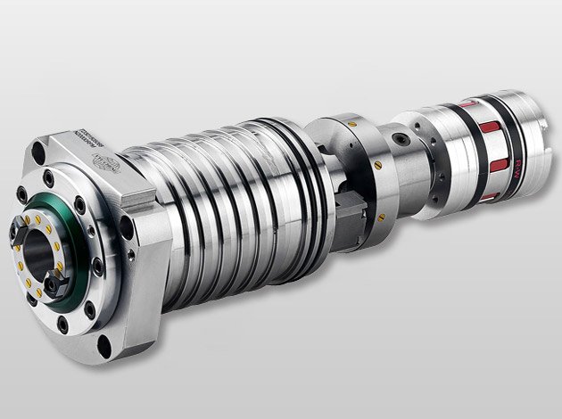
Concentric CNC components tolerances define the permissible deviation between cylindrical features sharing a common axis—critical for shafts, housings, and multi-diameter turned parts. When turn-mill or mill-turn operations produce complex geometries in one setup, maintaining concentricity across features becomes the primary driver of functional performance. OEM engineers evaluating suppliers must understand how geometry, material properties, process capability, and inspection methodology interact to determine what is achievable, repeatable, and economically viable at production scale.
Key Answer
Concentric CNC components tolerances typically range from ±0.01 mm for standard turned parts to ±0.005 mm for precision applications using turn-mill machining in one setup. Achievable results depend on material rigidity, workholding repeatability, thermal stability during machining, and CMM-based verification. Cross-drilled features, interrupted cuts, and length-to-diameter ratios above 6:1 introduce additional runout risk that requires process validation.
Why Concentricity Matters in Multi-Diameter Components
Concentricity error accumulates when multiple diameters on a shaft or housing fail to share a true common centerline. In high-speed rotating assemblies, bearing journals, seal surfaces, and coupling interfaces must maintain tight axial alignment to prevent vibration, premature wear, and power loss. For cross-drilled hydraulic manifolds or pump bodies, eccentric bores create turbulence and pressure drop that degrades system efficiency.
ISO 1101 defines concentricity as the condition where the median points of diametrically opposed elements of a surface of revolution lie within a cylindrical tolerance zone. Unlike runout, which measures surface deviation during rotation, concentricity evaluates the true position of derived median points—making it more stringent and harder to inspect without CMM equipment.
Geometry and Feature Interaction
Part geometry directly affects how tightly concentric tolerances can be held:
- Length-to-diameter ratio: Slender shafts deflect under cutting forces, introducing runout. Ratios above 6:1 typically require steady rests or tailstock support, adding setup complexity.
- Wall thickness variation: Thin-walled sections expand and contract during machining due to heat and clamping pressure. Residual stress after cutting can cause post-process distortion.
- Cross-drilled holes: Interrupted cuts through a rotating diameter create tool deflection and chatter. Cross-drilled turned parts often require secondary operations or specialized toolpaths to restore concentricity.
- Multiple diameters and transitions: Each diameter change introduces a new reference surface. Cumulative error grows unless all features are machined in one setup with minimal tool changes.
Turn-mill machines address many of these challenges by eliminating rechucking. When turning, milling, and drilling occur in one setup, the workpiece remains indexed to a single coordinate system, reducing stack-up error and improving mill-turn complex parts consistency.
Material Properties and Machinability
Material behavior under cutting forces directly affects concentricity:
- Aluminum alloys (6061, 7075): Soft and machinable but prone to thermal expansion. Tolerances of ±0.01 mm are standard; ±0.005 mm requires controlled feeds and flood coolant.
- Stainless steels (304, 316, 17-4PH): Work-hardening grades introduce tool wear and deflection. Rigid setups and carbide tooling are essential for ±0.01 mm concentricity.
- Titanium alloys (Ti-6Al-4V): Low thermal conductivity causes localized heating and dimensional shift. Achieving ±0.005 mm concentricity demands low cutting speeds, high-pressure coolant, and proven aerospace CNC machining protocols.
- Hardened steels (above 45 HRC): Grinding or hard-turning operations replace conventional turning. High-precision bore grinding can achieve ±0.003 mm but adds cost and cycle time.
According to Protolabs, standard CNC machining tolerances for metals fall within ±0.025 mm (±0.001 inch) without special callouts, but concentric features on shafts and housings often require tighter limits to ensure assembly fit and performance.
Process Capability: One Setup vs. Multi-Operation
How a part is fixtured and how many times it is rechucked determine concentricity limits:
| Method | Typical Concentricity | Key Limitation |
|---|---|---|
| Single-setup turn-mill | ±0.005 to ±0.01 mm | Machine thermal stability, spindle runout |
| Multi-operation turning | ±0.01 to ±0.02 mm | Rechucking error, datum shift between setups |
| Post-process grinding | ±0.003 to ±0.005 mm | Adds cost, requires hard fixturing |
| Manual secondary ops | ±0.02 mm or looser | Operator skill, fixture repeatability |
Single-setup machining eliminates the primary source of concentricity error: loss of datum reference. When a shaft is turned, cross-drilled, and milled without removal from the spindle, all features remain indexed to the original chuck grip. This is why turn-mill centers are preferred for concentric components in medical devices, hydraulic valves, and precision instrumentation.

Inspection and Verification Methodology
Concentricity cannot be measured with calipers or micrometers. Reliable verification requires:
- CMM with rotary table: The part is rotated while a probe measures radial deviation at multiple cross-sections. Software calculates the true median axis and compares it to the datum.
- Roundness tester: High-precision instruments measure form error and can derive concentricity when multiple diameters are assessed relative to a common axis.
- Functional gauging: Go/no-go fixtures or air gauges provide pass/fail feedback but do not quantify actual deviation.
ISO 1101 and ASME Y14.5 standards govern geometric dimensioning and tolerancing (GD&T) callouts. A concentricity callout on a drawing specifies the tolerance zone diameter and the datum feature. Suppliers must document measurement method, instrument uncertainty, and sample size to demonstrate process control.
For low-volume CNC production, first-article inspection with full CMM reporting validates the process. In high-volume manufacturing, statistical process control (SPC) tracks concentricity trends across production lots, flagging drift before parts fall out of specification.
Common Inspection Pitfalls
- Confusing runout with concentricity: Total runout is easier to measure but includes form error and surface finish. Concentricity isolates axis location only.
- Inadequate fixturing during measurement: If the part shifts or deflects on the CMM table, reported values are invalid.
- Ignoring temperature effects: Thermal expansion during measurement can introduce error. Parts and gages must stabilize at 20°C per ISO 1.
Design for Manufacturability: Practical Tolerancing
Designers can improve manufacturability and reduce cost by applying these principles:
- Use runout instead of concentricity where possible: If the functional requirement is smooth rotation, total runout is easier to achieve and verify.
- Assign tolerances based on function: Non-critical diameters can use ISO 2768-medium (±0.1 mm for small features). Reserve tight concentricity callouts for bearing seats and sealing surfaces.
- Specify datum features clearly: The datum must be a machinable, stable feature that the supplier can reference during setup and inspection.
- Avoid ultra-tight tolerances on long, slender parts: If L/D exceeds 8:1 and concentricity must be ±0.005 mm, consider splitting the part into an assembly or adding intermediate support features.
- Communicate inspection requirements early: If concentricity verification is critical, confirm the supplier has CMM capability before issuing the PO.
Checklist: Evaluating Supplier Capability for Concentric Components
- Does the supplier operate turn-mill or mill-turn machines for one-setup processing?
- What is the documented process capability (Cpk) for concentricity on similar materials and geometries?
- Is CMM inspection with GD&T reporting included in the standard workflow?
- How does the supplier control thermal drift during long production runs?
- Are cutting tools and workholding fixtures regularly validated for runout?
- Can the supplier provide first-article inspection reports with full dimensional data?
- What is the typical lead time for tight-tolerance concentric parts in your required material?
For complex assemblies requiring multiple concentric features, request a process FMEA (Failure Mode and Effects Analysis) that identifies risks and mitigation strategies. Suppliers with ISO 9001 or AS9100 certification typically maintain documented procedures for process validation and control.
Frequently Asked Questions
What is the difference between concentricity and runout tolerances?
Concentricity measures the true position of the median axis of a cylindrical feature relative to a datum axis, independent of surface irregularities. Runout measures the total variation of a surface as the part rotates, including form error, wobble, and axis deviation. Runout is easier to inspect with a dial indicator but less precise. Concentricity requires CMM measurement and is specified when the functional requirement is true axial alignment, such as in high-speed rotating assemblies or hydraulic sealing surfaces.
Can concentric CNC components tolerances be held across cross-drilled features?
Yes, but it requires careful toolpath planning and rigid setups. Cross-drilling interrupts the cutting edge, causing tool deflection and potential chatter. Turn-mill machines can orient the part and drill perpendicular to the rotation axis in one setup, maintaining the datum reference. Post-drilling, a finish turning pass may be needed to restore concentricity. Typical achievable tolerance after cross-drilling is ±0.01 mm with proper compensation; tighter limits may require grinding or EDM for the cross-hole.
What concentricity tolerance is typical for aerospace shafts and hydraulic components?
Aerospace transmission shafts and actuator rods typically specify ±0.005 to ±0.01 mm concentricity between bearing journals. Hydraulic valve spools and pump shafts may require ±0.003 to ±0.005 mm to minimize leakage and ensure smooth operation under pressure. These tolerances demand turn-mill processing, post-process grinding, or hard-turning with CBN tooling. Suppliers must demonstrate process capability through first-article inspection and ongoing SPC monitoring to meet aerospace quality standards.
How does material hardness affect achievable concentricity?
Softer materials like aluminum and brass are easier to machine with tight concentricity because cutting forces are lower and tool deflection is minimized. Hardened steels above 45 HRC require grinding or hard-turning, which can achieve ±0.003 to ±0.005 mm but at higher cost. Stainless steels and titanium work-harden during cutting, increasing tool wear and deflection, which degrades concentricity unless cutting parameters are optimized and tool paths are validated. Material selection should balance functional requirements with manufacturability and cost.
What inspection equipment is required to verify concentricity to ±0.005 mm?
Coordinate measuring machines (CMM) with rotary tables and GD&T software are the standard for verifying concentricity to ±0.005 mm or tighter. The CMM probes multiple points around each diameter at several axial positions, calculates the median axis, and compares it to the datum. Instrument uncertainty must be at least 10 times better than the tolerance (±0.0005 mm for ±0.005 mm tolerance). Roundness testers with multi-axis capability can also verify concentricity but are less common in general machining environments.
Should I specify concentricity or positional tolerance for CNC shafts?
Use concentricity when the functional requirement is true median axis alignment, such as in high-precision bearings or sealing surfaces. Specify positional tolerance (with MMC or LMC modifiers) when the goal is to control the location of a feature relative to a datum for assembly fit. Positional tolerances allow bonus tolerance when features are not at their size limits, making them more cost-effective for many applications. Concentricity is more restrictive and harder to inspect, so reserve it for cases where axis alignment is critical to performance.
Conclusion
Concentric CNC components tolerances are governed by the interaction of geometry, material behavior, process capability, and inspection rigor. Turn-mill machining in one setup delivers the tightest, most repeatable results by eliminating rechucking error and maintaining a single datum reference throughout all operations. OEM teams evaluating suppliers should focus on documented process capability, CMM-based verification, and evidence of thermal and tool management in production. For parts requiring ±0.005 mm concentricity or tighter, request first-article inspection reports and ongoing SPC data to confirm the supplier can deliver consistent results at scale. If your project involves complex concentric features, upload your drawings for a detailed tolerance and process review.
Sources
- Protolabs – Fine-Tuning Tolerances for CNC Machined Parts: https://www.protolabs.com/resources/design-tips/fine-tuning-tolerances-for-cnc-machined-parts/
- Protolabs Network (Hubs) – CNC Machining ISO-Based Tolerances & Finishes: https://www.hubs.com/knowledge-base/cnc-machining-iso-based-tolerances-and-finishes/
- Pinnacle Metal – Essential Guide to Understanding Machining Tolerances: https://www.pinnaclemetal.com/essential-guide-to-understanding-machining-tolerances-in-manufacturing/
- Modus Advanced – Tight Tolerance Machined Parts Design Guidelines: https://www.modusadvanced.com/resources/blog/tight-tolerance-machined-parts-design-for-manufacturing-guidelines