
- Shaft
- Molds&Tools
- Hydraulics And Pump
- Hair transplant needle
- Hydraulics And Pump
- Precision CNC Shaft Machining Manufacturer for High Performance Applications
- Energy Industry CNC Machining Parts Supplier
- Aerospace Structural Components for OEM Programs
- Aerospace Structural Components for OEM Programs
- Automotive & EV CNC Machining Parts Supplier for OEM and Tier 1
- Medical Device CNC Machining Services
DFM for Aerospace Prototype Machining: Reducing Risk Before Production

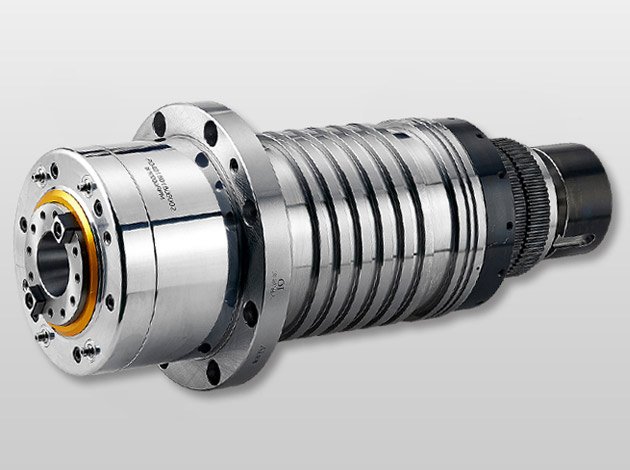
Aerospace prototype machining transforms complex CAD geometry into physical parts that must meet exacting standards while proving manufacturable at scale. DFM for aerospace prototype machining addresses the gap between design intent and production reality, identifying geometry, tolerance, and material choices that drive cost, cycle time, and inspection burden before committing to tooling or batch runs.
Key answer: DFM for aerospace prototype machining evaluates part geometry, tolerance allocation, material selection, and inspection accessibility during the prototype phase. Early identification of undercuts, thin walls, deep pockets, and tight tolerance stacks reduces rework, shortens cycle time, and ensures dimensional stability when scaling from prototype to production. This front-loaded review mitigates cost and schedule risk inherent in aerospace components machined from titanium, Inconel, and other difficult materials.
Why DFM Matters in Aerospace Prototype Development
Aerospace components operate under thermal, vibrational, and structural loads that demand precise geometry and material integrity. Unlike commercial products, aerospace prototypes often serve as pathfinders for qualification programs, meaning defects discovered late cascade into certification delays and retooling expense.
DFM analysis during prototyping addresses three risk categories:
- Geometric feasibility: Identifying features that exceed tool reach, require custom fixturing, or demand non-standard cutter geometry.
- Tolerance realism: Assessing whether specified tolerances can be held given material behavior, thermal expansion, and machine capability.
- Inspection accessibility: Ensuring critical dimensions and surface finishes can be measured with standard CMM or optical systems without custom fixturing.
A prototype that machines successfully but cannot be inspected or reproduced at volume delivers limited value. Aerospace CNC machining benefits from early collaboration between design, manufacturing, and quality teams to surface these constraints before first article inspection.
Material-Specific DFM Considerations for Aerospace Prototypes
Aerospace prototypes frequently use titanium alloys (Ti-6Al-4V, Ti-6-2-4-2) and nickel superalloys (Inconel 718, Inconel 625) chosen for strength-to-weight ratio and high-temperature performance. These materials impose distinct manufacturability constraints.
Titanium Alloys
Titanium’s low thermal conductivity concentrates heat at the cutting edge, accelerating tool wear and requiring conservative feed rates. Thin-walled titanium sections deflect under cutting forces, making dimensional stability difficult without intermediate stress relief or adaptive fixturing. DFM reviews should flag:
- Wall thickness below 1.5 mm in unsupported spans
- Deep pockets where chip evacuation becomes restricted
- Blind holes with depth-to-diameter ratios exceeding 5:1
Nickel Superalloys
Inconel work-hardens rapidly, forming a strain-hardened layer that dulls subsequent tool passes. Five-axis continuous machining reduces repositioning but increases programming complexity. DFM for Inconel prototypes prioritizes:
- Minimizing sharp internal corners that trap heat and accelerate tool wear
- Specifying radii rather than sharp edges wherever structural analysis permits
- Allocating machining time for frequent tool changes and in-process inspection
Understanding these material behaviors during prototype design prevents discovering them during a failed first article.
Geometry and Tolerance Allocation in Prototype DFM
Aerospace components often feature complex contours, intersecting holes, and tight positional tolerances driven by assembly interfaces and load paths. DFM reviews translate these requirements into machinable geometry.
Feature Accessibility and Tool Reach
Five-axis machining expands geometric freedom but does not eliminate access constraints. Deep cavities, narrow slots, and undercut features still require tool clearance and chip evacuation paths. Prototypes with inaccessible features force custom tooling or multi-setup sequences that increase cost and error risk.
Tolerance Stacks and Datum Strategy
Aerospace drawings frequently specify GD&T callouts referencing multiple datums. Prototype machinists must establish these datums through fixturing and probing, introducing measurement uncertainty at each step. DFM reviews should:
- Minimize datum references to features machinable in a single setup
- Avoid tolerance chains that accumulate across multiple operations
- Specify inspection datums that align with machining datums
A prototype designed with a clear datum hierarchy machines faster and inspects with greater confidence than one requiring complex coordinate transformations.
Inspection and Documentation Requirements
Aerospace prototypes generate first article inspection reports (FAIRs) that document conformance to every drawing callout. DFM for aerospace prototype machining anticipates inspection needs during design, ensuring critical features remain measurable.
| Feature Type | Inspection Challenge | DFM Mitigation |
|---|---|---|
| Internal diameters <5 mm | CMM probe access limited | Specify pin gauge acceptance or optical measurement |
| Surface finish in deep pockets | Profilometer reach constrained | Provide witness surfaces in accessible locations |
| Positional tolerance <0.05 mm | Fixture repeatability critical | Design locating features for kinematic constraint |
| Contoured surfaces | Requires CAD comparison scan | Ensure scan accessibility without disassembly |
Prototypes that defer inspection strategy to post-machining often require rework or drawing revisions to achieve measurable conformance.

Scaling from Prototype to Production
A successful prototype proves geometric feasibility but does not guarantee production readiness. DFM analysis during prototyping should anticipate batch manufacturing constraints.
Fixturing and Setup Reduction
Prototype machining often accepts multi-setup sequences to prove out geometry. Production economics demand setup consolidation. DFM reviews identify opportunities to reorient features, combine operations, or simplify datum schemes before tooling investment.
Tool Life and Cycle Time
Prototype programs often use conservative feeds and speeds to ensure first-piece success. Production requires predictable tool life and cycle time. DFM feedback from prototype runs informs material removal strategies, tool path optimization, and preventive tool change intervals for batch work.
Material Utilization
Aerospace prototypes frequently machine from oversized billet to accommodate design iteration. Production demands tighter nesting and near-net-shape starting stock. Early DFM collaboration with CNC machining capabilities teams identifies stock size optimization opportunities before committing to supply agreements.
Practical DFM Checklist for Aerospace Prototype Machining
Use this checklist during prototype design reviews to surface manufacturability risks early:
- Verify all critical features accessible with standard 5-axis tool lengths and holder clearances
- Confirm wall thickness >2 mm in titanium, >1.5 mm in aluminum for unsupported sections
- Limit depth-to-diameter ratios to 5:1 for drilled holes without special tooling
- Specify corner radii ≥0.5 mm in pockets to reduce tool wear and stress concentration
- Align inspection datums with machining setup datums
- Document acceptable measurement methods for features <5 mm or in restricted access areas
- Review tolerance stack-ups across multi-setup operations
- Confirm material certifications and traceability requirements match supplier capabilities
This checklist complements formal design reviews and first article planning, providing a manufacturability lens before committing to prototype builds.
Frequently Asked Questions
What tolerances are realistic for aerospace prototype machining in titanium?
Standard CNC machining holds ±0.025 mm on linear dimensions and ±0.05 mm on positional tolerances in titanium alloys without secondary grinding. Tighter tolerances require temperature-controlled environments, in-process measurement, and iterative tool path compensation. Prototypes specifying ±0.01 mm should budget for extended cycle time and potential dimensional drift during stress relief.
How does 5-axis machining reduce DFM risk in aerospace prototypes?
Five-axis machining consolidates setups, reducing cumulative datum error and fixturing complexity. Continuous tool orientation improves surface finish on contoured geometry and allows shorter, stiffer tools for better dimensional control. For aerospace prototypes with complex contours or intersecting features, 5-axis CNC machining reduces rework risk by machining complete features in one setup.
When should prototype DFM reviews involve the supplier?
Engage suppliers during concept design when geometry, material, or tolerance requirements approach manufacturing limits. Early collaboration surfaces fixturing needs, tool availability, and inspection constraints before drawings freeze. Supplier DFM input is especially valuable for materials like Inconel or when prototypes must scale to high-rate production.
What inspection documentation should aerospace prototypes include?
Aerospace prototypes require first article inspection reports documenting every drawing dimension, GD&T callout, and material certification. Include CMM measurement data, surface finish readings, and material test certificates traceable to heat lot. For guidance on quality documentation standards, refer to aerospace prototype machining quality control frameworks aligned with AS9102 requirements.
How do material costs affect DFM decisions in aerospace prototypes?
Titanium and Inconel raw material costs justify DFM emphasis on near-net-shape stock, efficient tool paths, and minimized scrap. Prototype designs with high buy-to-fly ratios (material removed vs. final part weight) should explore alternative orientations, feature consolidation, or starting stock geometry to reduce waste. CNC machining cost analysis during DFM reviews quantifies material waste impact before committing to prototype builds.
Can DFM analysis predict production cycle time from prototype data?
Prototype cycle time provides a baseline but typically understates production time due to conservative parameters, manual inspection intervals, and setup optimization not yet implemented. DFM reviews use prototype data to identify bottleneck operations, tool life constraints, and inspection duration, then model production scenarios with consolidated setups, optimized feeds, and statistical process control replacing 100% inspection.
Conclusion
DFM for aerospace prototype machining bridges design intent and manufacturing reality, surfacing geometric, tolerance, and material constraints before they become costly surprises. Early collaboration between engineering and machining teams reduces rework, shortens first article timelines, and ensures prototypes scale predictably to production volumes. For aerospace components machined from titanium, Inconel, and other demanding materials, front-loaded DFM analysis is a risk mitigation investment that pays dividends throughout the product lifecycle. To discuss your aerospace prototype machining requirements, upload your drawings for a detailed manufacturability review.