
- Shaft
- Molds&Tools
- Hydraulics And Pump
- Hair transplant needle
- Hydraulics And Pump
- Precision CNC Shaft Machining Manufacturer for High Performance Applications
- Energy Industry CNC Machining Parts Supplier
- Aerospace Structural Components for OEM Programs
- Aerospace Structural Components for OEM Programs
- Automotive & EV CNC Machining Parts Supplier for OEM and Tier 1
- Medical Device CNC Machining Services
DFM for Aerospace Titanium CNC Machining: Reducing Risk Before Production

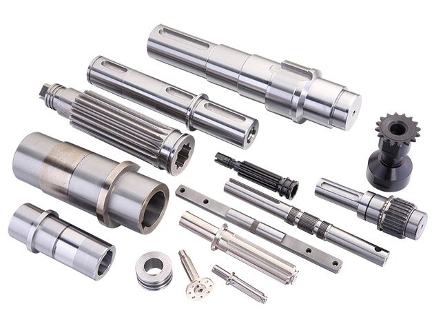
Key Answer: Design-for-manufacturability (DFM) for aerospace titanium CNC machining translates early design choices into production certainty. By addressing tool access, thermal gradients, material flow, and inspection evidence during design review—not after tooling—OEM teams reduce scrap risk, inspection cycles, and time to rate production.
Why DFM for Aerospace Titanium CNC Machining Matters Now
Aerospace titanium components—engine casings, structural brackets, fastener bosses—operate under extreme thermal, vibrational, and fatigue loads. A design that looks feasible on paper can become a manufacturing bottleneck if it ignores material behavior, tool geometry, or inspection accessibility.
5-axis CNC machining for aerospace components has expanded design freedom, but that freedom creates risk. Each additional axis, each complex undercut, and each high-tolerance pocket increases the number of setups, tool changes, and thermal cycles—all of which compound material-induced variability in titanium.
DFM for aerospace titanium CNC machining is not a checklist; it is a bridge between design intent and manufacturing reality. It asks: Can the toolpath access this geometry without collision? Will thermal stress induce residual strain that violates dimensional tolerance? Is the surface finish inspectable with standard equipment?
Material Behavior: Why Titanium Demands Different Design Rules
Titanium (Ti-6-4, Ti-5-8-5, Inconel 718) behaves differently from aluminum or steel during machining:
- Low thermal conductivity: Heat concentrates at the tool-chip interface, causing rapid tool wear and work-hardening. Conventional feeds and speeds for steel fail; cutting speeds are 30–50% lower.
- High spring-back: Titanium rebounds elastically after cutting, changing final dimensions and surface finish if tool pressure is not tightly controlled.
- Chip welding: At high temperatures, titanium chips weld to the tool, increasing drag and tool breakage. Coolant delivery and chip evacuation are non-negotiable.
- Residual stress: Shallow cuts and rapid tool changes create uneven thermal gradients, leaving tensile residual stress that can initiate fatigue cracks under service load.
These behaviors mean that DFM for aerospace titanium CNC machining must front-load decisions about wall thickness, pocket depth, internal radii, and draft angles—before design is released to manufacturing.
Five Design Choices That Impact Manufacturability
1. Wall Thickness and Pocket Depth Ratios
Thin walls (< 1.5 mm) flex under cutting load, causing chatter and dimensional drift. Pockets deeper than 5× the tool diameter increase tool deflection and require mid-depth tool changes to avoid excessive runout.
DFM guidance: Maintain wall thickness ≥ 1.5 mm for titanium; limit pocket depth to 4× tool diameter per pass. If deeper pockets are structural requirements, break them into 2–3 setups with intermediate inspection.
2. Internal Radii and Corner Geometry
Sharp internal corners (r < 0.5 mm) require tiny end mills that deflect easily and break quickly in titanium. They also create stress concentrators in service. Large radii (r ≥ 2 mm) improve tool life and reduce residual stress, but may conflict with fit or assembly requirements.
DFM guidance: Specify minimum radii of 1.0–1.5 mm for internal corners; larger where service loads permit. Communicate the trade-off between corner sharpness and tool cost to the design team early.
3. Boss and Hole Placement for Tool Access
Bosses and threaded holes placed near pocket edges or deep inside cavities require angled toolpaths or secondary setups. Each additional setup increases scrap risk (setup error, part movement) and lead time.
DFM guidance: Locate bosses and holes where standard vertical or 5-axis interpolation can reach them in one setup. If near edges, add 0.5 mm of clearance between pocket wall and boss base to avoid tool collision.
4. Surface Finish Specification and Inspection Method
Tight surface finishes (Ra ≤ 0.4 µm) on titanium demand slow feeds, frequent tool changes, and burnishing passes—adding 20–40% to cycle time. More importantly, if the finish specification is not tied to a defined inspection method (contact profilometer, optical surface analyzer, sample plan), disputes over acceptance arise during first-article inspection (FAI).
DFM guidance: Specify surface finish only where function requires it (bearing surfaces, seal seats). Define inspection method and sample density in the purchase order. Default to Ra 0.8–1.6 µm for structural titanium unless aerodynamic, hydraulic, or fatigue data supports tighter tolerances.
5. Thermal Stress and Multi-Axis Sequencing
5-axis machining can complete complex geometry in one setup, but if that setup requires continuous high-speed cutting at multiple angles, thermal gradients create residual stress. The part cools unevenly, and dimensions shift post-machining.
DFM guidance: Break long 5-axis cycles into 2–3 roughing passes with cooldown between them; schedule finishing passes after the part reaches thermal equilibrium. Communicate critical dimensions that are sensitive to residual stress to the machine shop so they can prioritize cooling strategy.
DFM Decision Framework: From Design to First Article
Early DFM review prevents late-stage surprises. This framework applies at three gates:
Gate 1: Conceptual Design (30% complete)
Question: Does the geometry fit within the machine envelope and standard tool library? Are there competing requirements (finish vs. tool access) that need trade-off discussion now?
- Sketch the part in section; identify deep pockets, internal features, and boss locations.
- Confirm the machine shop has 5-axis or 3-axis capability and the tool diameter range needed.
- Flag geometry that cannot be done in one setup; estimate setup count and alert the program manager to lead-time risk.
Gate 2: Detailed Design (80% complete)
Question: Are all tolerances justified by function? Are surface finishes and material callouts compatible with DFM?
- Review GD&T on critical dimensions; confirm that frame-of-reference and datum precedence are achievable in two setups or fewer.
- Cross-check surface finish requirements against machining cost; negotiate down where function allows.
- Confirm material heat-treat specs do not conflict with post-machining residual stress (e.g., stress-relief anneal after machining for critical components).
Gate 3: Release to Manufacturing (100% complete)
Question: Does the production drawing pack include DFM callouts that reduce ambiguity?
- Add notes on pocket depth limits, wall thickness minimums, and internal radii.
- Define inspection method and sample plan for surface finish and dimensional tolerance.
- Provide material certs and machine shop capability summary in the RFQ to expedite quote turnaround.
Practical DFM Checklist for Aerospace Titanium Machining
Before releasing a design to manufacturing, confirm:
- Wall thickness ≥ 1.5 mm; pocket depth ≤ 4× tool diameter per pass.
- Internal radii ≥ 1.0 mm; communicate trade-offs with design team if tighter radii are structural requirements.
- All bosses and holes are accessible in 1–2 setups; no blind internal threads requiring special tooling.
- Surface finish specs are functional, not arbitrary; each specification includes inspection method and acceptance criteria.
- Critical dimensions for fit or fatigue are on the same datum plane where possible; minimize setup count.
- Material grade, heat-treat condition, and any post-machining stress-relief are documented on the drawing.
- Tolerance stack-up has been reviewed for residual stress and thermal drift during multi-axis cutting.
- RFQ includes machine shop capability summary (5-axis availability, tool diameter range, coolant system type).
Frequently Asked Questions
Q: How does 5-axis machining change DFM for titanium?
5-axis reduces setup count and tool changes, but increases thermal input per cycle. DFM guidance shifts from minimizing geometry complexity to managing thermal gradients and residual stress. Multi-angle cutting in a single setup can induce uneven cooling; splitting the cycle into roughing and finishing passes with cooldown helps.
Q: When should we specify stress-relief annealing after machining?
Stress-relief is recommended for high-fatigue components (engine casings, structural brackets) where residual tensile stress can initiate cracks under cyclic load. It adds 10–20% to lead time and cost. Consult fracture mechanics or fatigue data for your application; do not specify blanket anneals without functional justification.
Q: What is the typical setup count for a complex aerospace titanium bracket in 5-axis CNC?
A single-piece bracket with pockets, bosses, and tight GD&T typically requires 2–3 setups: one for primary faces and roughing; one or two for finishing and secondary features. Each setup adds ~30–60 min of machine time plus load/unload and inspection. Early DFM review can sometimes reduce this to 2.
Q: Can we tighten surface finish specs to ensure better fatigue performance?
Surface finish below Ra 0.4 µm does not reliably improve fatigue life unless the component is also shot-peened or stress-relieved. Tighter finishes add 20–40% to cycle time without functional benefit in most aerospace structures. Specify finish based on aerodynamic, hydraulic, or bearing requirements—not as a proxy for quality.
Q: How do we handle complex internal geometry that does not fit a single 5-axis toolpath?
Break it into 2–3 setups with different part orientations, or use multiple tools (roughing end mill, corner radius tool, finishing end mill) in sequence. First-article quality control should include intermediate inspection between setups to catch drift early.
Q: What inspection evidence do we need to accept a titanium aerospace part from the machine shop?
Minimum: dimensional CMM report on all GD&T callouts, surface finish on critical surfaces (profile report, not just averages), and material cert (chemistry, hardness). For critical components: fractography or non-destructive testing per the purchase order. Define acceptance criteria before machining, not after.
Conclusion: DFM as Cost and Risk Management
DFM for aerospace titanium CNC machining is an engineering discipline, not a constraint. It translates design intent into production reality by addressing tool access, thermal behavior, and inspection evidence early—when changes are cheap. By the time a part reaches the machine, the critical decisions have already been made.
OEM teams, sourcing managers, and Tier 1 procurement leaders who invest time in early DFM review—tool access analysis, tolerance justification, material callouts, inspection planning—see measurable returns: shorter lead times, lower scrap rates, faster first-article acceptance, and confidence in scale-up.
The machine shop is your partner in this process. Sharing your design and DFM requirements early—before commitment to tooling—allows the shop to flag feasibility issues, suggest geometry changes, and provide realistic cost and lead-time targets. That transparency accelerates design validation and reduces post-quote surprises.