
- Shaft
- Molds&Tools
- Hydraulics And Pump
- Hair transplant needle
- Hydraulics And Pump
- Precision CNC Shaft Machining Manufacturer for High Performance Applications
- Energy Industry CNC Machining Parts Supplier
- Aerospace Structural Components for OEM Programs
- Aerospace Structural Components for OEM Programs
- Automotive & EV CNC Machining Parts Supplier for OEM and Tier 1
- Medical Device CNC Machining Services
DFM for Custom Lathe Parts: Reducing Risk Before Production

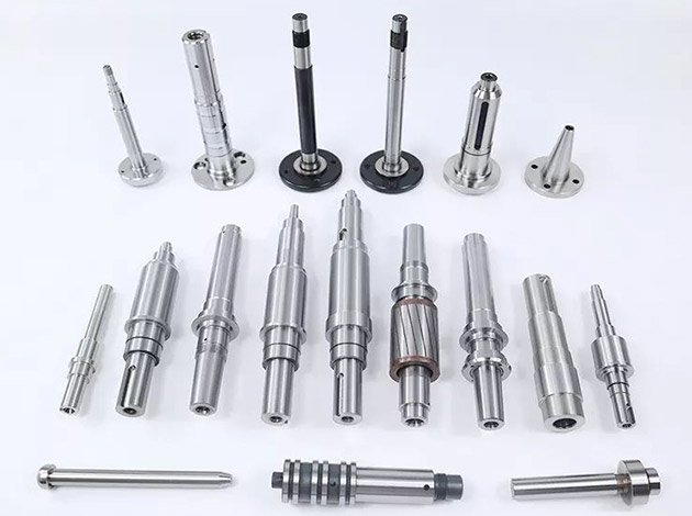
Turning operations deliver rotational components faster and more cost-effectively than milling, but design choices made upstream determine whether a custom lathe part can be produced reliably at scale. Poor DFM for custom lathe parts drives rework cycles, inspection failures, and unexpected tooling costs. Engineering teams that integrate manufacturability principles early reduce lead times, improve geometric control, and eliminate late-stage design changes that delay production ramp-up.
Key answer: DFM for custom lathe parts focuses on feature accessibility, workholding stability, concentricity control, and surface finish achievability. Early collaboration on material selection, tolerance allocation, and datum strategy prevents machining conflicts, reduces setup count, and ensures inspection methods align with geometric requirements. This approach lowers per-part cost and supports scalable batch consistency across custom motor shafts and precision turned components.
Why Manufacturability Analysis Matters for Turned Components
Lathe operations constrain geometry differently than milling. A shaft design that looks feasible in CAD may require multiple setups, custom fixtures, or secondary operations that multiply cost and introduce alignment error. Turned parts depend on rotational symmetry and axial access, so features that interrupt these principles—cross holes near shoulders, internal threads at maximum depth, or non-concentric features—complicate programming and increase cycle time.
Manufacturability reviews identify conflicts between design intent and machining reality. Common issues include:
- Insufficient tool clearance at shoulders or fillets
- Tolerance stack-ups that exceed lathe capability without secondary grinding
- Internal features requiring custom boring bars or limited access tooling
- Surface finish specifications that demand polishing or hard turning after heat treatment
- Datum references that cannot be reliably established during setup
Addressing these conflicts before quoting prevents mid-project design revisions and protects production schedules.
Material and Heat Treatment Decisions That Affect Turning
Material machinability directly influences cycle time, tool wear, and achievable surface finish. Free-machining alloys like 12L14 or 303 stainless reduce cutting forces and extend tool life, but limit strength and corrosion resistance. Harder materials like 17-4PH stainless or 4140 pre-hard steel require carbide inserts, slower feeds, and more frequent tool changes. Heat-treated components introduce distortion risk, so datum surfaces and tight-tolerance features should be finished after thermal processing.
Heat treatment timing affects concentricity. Shafts requiring through-hardening or carburizing must account for dimensional change and residual stress. Finishing operations—centerless grinding, hard turning, or lapping—restore geometric control after heat treatment but add cost. Design reviews should confirm whether final tolerances can be held through heat treatment or require post-heat machining allowances.
Geometric Features and Tolerance Allocation
Concentricity, runout, and cylindricity requirements define inspection and process planning. Lathe chucking naturally maintains coaxiality between features machined in one setup, but multi-setup operations introduce alignment error. Designs that specify tight concentricity between features requiring separate setups—such as a splined end and a threaded opposite end—should evaluate whether end-to-end tolerance can be met without indicating or custom fixturing.
Tolerance allocation should match process capability. CNC turning typically achieves ±0.005 mm diameter tolerance and 0.01 mm concentricity in single-setup operations. Tighter tolerances require grinding, honing, or precision boring. Thread classes, keyway positions, and cross-hole locations all carry specific machining constraints that affect cost and cycle time.
Common Geometric Conflicts
| Feature Type | Manufacturability Risk | DFM Solution |
|---|---|---|
| Deep bores with tight diameter tolerance | Tool deflection and chatter limit depth-to-diameter ratio | Specify boring bar access or split part into assembly |
| Sharp internal corners | Tool radius prevents true sharp corner | Add 0.5–1.0 mm fillet radius to match tool geometry |
| Thin-wall sections under 2 mm | Workholding pressure and cutting forces cause deflection | Use tailstock support or design thicker nominal wall |
| External threads to shoulder | Threading tool requires runout clearance | Add 2–3 mm relief groove before shoulder |
Design Checklist for DFM in Custom Lathe Parts
Use this checklist during design reviews to identify manufacturability issues before quoting:
- Confirm all features are accessible with standard tooling or specify custom tool requirements
- Verify shoulder and fillet radii match available insert geometry (typically 0.4–3.0 mm)
- Check that thread relief grooves provide adequate tool clearance
- Ensure bore depth-to-diameter ratios stay below 5:1 without support
- Specify datums that can be reliably established during first and subsequent setups
- Allocate tighter tolerances only to functionally critical dimensions
- Confirm material heat treatment sequence aligns with tolerance requirements
- Identify cross holes, flats, or keyways that require secondary milling operations
- Review surface finish callouts against material machinability and tool capability
This systematic approach reduces quotation revisions and shortens engineering iteration cycles. OEM teams working with precision manufacturing systems benefit from early supplier engagement during concept and detailed design phases.

Workholding and Setup Strategy
Setup count directly affects cost and geometric accuracy. Each workholding change introduces alignment error and extends cycle time. Shaft designs that allow all critical features to be machined from one end minimize setups and preserve concentricity. When features require access from both ends, specify looser tolerances on non-critical dimensions to avoid expensive indicating and fixturing.
Workholding method depends on part geometry and production volume. Collet chucks suit high-volume production of bar-fed shafts with consistent diameters. Three-jaw chucks accommodate larger diameter variation but introduce modest runout. Fixtures with V-blocks or custom soft jaws support non-cylindrical or interrupted surfaces. Long, slender shafts need tailstock or steady-rest support to prevent deflection during cutting.
Impact of Setup Decisions on Lead Time and Cost
Single-setup operations complete faster and yield tighter concentricity than multi-setup processes. Parts requiring turning, milling, grinding, and heat treatment follow longer process routes and accumulate more handling time. Design simplification—eliminating secondary features or relaxing non-functional tolerances—can reduce setup count and accelerate delivery. This consideration becomes critical when scaling from prototype to production volumes.
Inspection and Quality Verification Planning
Inspection strategy must align with specified tolerances and geometric controls. Simple diameter and length measurements use micrometers or calipers, but concentricity, cylindricity, and positional tolerance require CMM or dedicated runout fixtures. Designs specifying GD&T callouts should confirm that the manufacturer’s measurement capability matches the tolerance band.
First-article inspection (FAI) verifies process capability before production begins. This step identifies dimensional drift, tool wear patterns, or fixturing issues that could affect batch consistency. Production runs benefit from in-process gauging—diameter checks after roughing passes, runout verification before final machining—that catches deviations before parts leave the machine. Understanding these quality gates helps engineering teams set realistic tolerances and avoid over-specification.
For components in regulated industries, traceability and material certifications add cost and lead time. Teams sourcing for aerospace CNC machining or medical device manufacturing should clarify documentation requirements during the RFQ phase.
Scaling from Prototype to Production
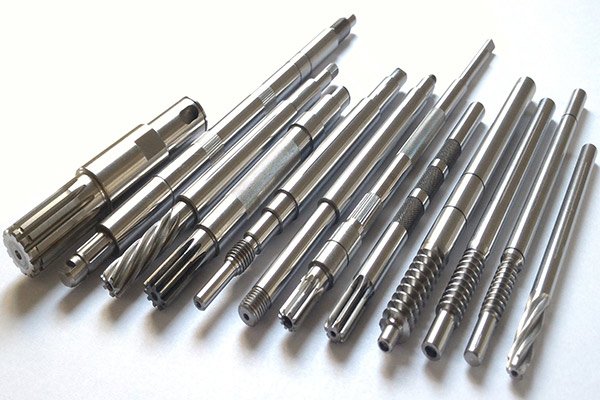
Prototyping tolerates manual setups, custom tooling, and extended cycle times. Production requires repeatable processes, standard tooling, and predictable material flow. Designs optimized for prototype machining—tight tolerances across all dimensions, exotic materials, or features requiring specialized equipment—often fail to scale economically.
Transitioning to production involves process refinement: substituting standard tooling for custom inserts, optimizing feeds and speeds, and implementing poka-yoke fixturing. Some designs require value engineering to replace difficult features with functionally equivalent alternatives that machine faster. Early supplier collaboration during the design phase identifies these opportunities before tooling investment locks in a costly process.
Frequently Asked Questions
What tolerance range is achievable in standard CNC turning without secondary grinding?
CNC turning operations typically hold ±0.005 mm on diameters and ±0.025 mm on lengths in single-setup work. Concentricity of 0.01 mm is achievable between features machined in one setup. Tighter tolerances—0.002 mm diameter or 0.005 mm concentricity—require grinding, honing, or precision boring. Heat-treated shafts that must meet sub-0.01 mm tolerances need post-heat finish operations to correct distortion.
How do I specify surface finish requirements for custom lathe parts?
Surface finish depends on material, tooling, and cutting parameters. Standard turning achieves Ra 1.6–3.2 µm. Finer finishes—Ra 0.8 µm or better—require diamond tooling, hard turning, or grinding. Specify finish only where functionally necessary; cosmetic surfaces can accept coarser finishes that reduce cycle time. Provide roughness values rather than descriptive terms, and confirm the manufacturer’s measurement method aligns with your callout standard.
When should cross holes or keyways be added after turning?
Cross holes, flats, keyways, and other non-rotational features require secondary milling operations. These features break the symmetry that makes turning efficient, so they add setup time and alignment steps. If possible, position secondary features to allow milling while the shaft remains in the lathe’s sub-spindle or live tooling station. Otherwise, plan for transfer to a mill, which introduces fixturing cost and alignment tolerance.
What material properties affect machinability and cycle time in turning?
Free-machining grades like 12L14 steel or 303 stainless contain additives that improve chip breaking and reduce cutting forces, lowering cycle time and tool wear. Harder materials—4140 pre-hard, 17-4PH, or titanium—require carbide or ceramic inserts, slower speeds, and more frequent tool changes. Stringy materials like austenitic stainless or pure aluminum require chip management strategies. Consult with your manufacturing partner to select materials that balance performance and machinability.
How does heat treatment sequence affect dimensional accuracy?
Heat treatment induces distortion through phase transformation, thermal expansion, and residual stress relief. Carburizing, through-hardening, and stress relieving all change dimensions and can introduce warping. Parts requiring tight tolerances after heat treatment must include machining allowances—typically 0.25–0.5 mm per surface—so final dimensions can be achieved through post-heat grinding or hard turning. Specify critical datums and tolerances to be finished after thermal processing.
What design features most commonly increase cost in custom lathe parts?
Features that increase cost include deep internal bores requiring long-reach tooling, interrupted cuts that cause chatter, tight concentricity between features requiring separate setups, non-standard thread forms, and surface finishes below Ra 0.8 µm. Secondary operations—cross drilling, broaching, grinding—add setup time and handling. Designs that allow single-setup machining with standard tooling minimize cost. Related guidance appears in our article on custom lathe parts cost variables.
Conclusion
Effective DFM for custom lathe parts reduces risk by aligning design geometry with machining constraints, material behavior, and inspection capability. Engineering teams that engage manufacturing partners during design prevent costly revisions, improve concentricity and surface quality, and accelerate time to production. Systematic review of tolerances, workholding strategy, and secondary operations ensures turned components meet functional requirements without over-specification that inflates cost. Scalable manufacturing depends on designs that balance performance with process reality.
Sources
- Protolabs, DFM Guidelines for CNC Machining, https://www.protolabs.com/resources/design-for-machining-toolkit/
- Hubs (Protolabs Network), How to Design Parts for CNC Machining, https://www.hubs.com/knowledge-base/how-design-parts-cnc-machining/