
- Shaft
- Molds&Tools
- Hydraulics And Pump
- Hair transplant needle
- Hydraulics And Pump
- Precision CNC Shaft Machining Manufacturer for High Performance Applications
- Energy Industry CNC Machining Parts Supplier
- Aerospace Structural Components for OEM Programs
- Aerospace Structural Components for OEM Programs
- Automotive & EV CNC Machining Parts Supplier for OEM and Tier 1
- Medical Device CNC Machining Services
Mill Turn Complex Parts Quality Control: An OEM Acceptance Checklist

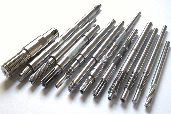
When accepting mill turn complex parts from a supplier, generic inspection reports and vague conformance statements create risk. OEM engineers and quality teams need concrete evidence that turned features, milled geometries, cross drilled holes, and concentric dimensions all meet specification—especially when those features were produced in one setup to maximize accuracy. This checklist translates print requirements into verifiable acceptance criteria, measurement protocols, and documentation standards that protect both prototype validation and scaled production.
Key answer: Effective mill turn complex parts quality control requires dimensional verification of turned and milled features using calibrated coordinate measuring machines or optical comparators, material certification matching print callouts, surface finish measurement on critical functional surfaces, first article inspection reports documenting setup capability, and batch traceability linking inspection data to specific production runs. Each acceptance decision must rest on objective measurement evidence, not supplier assertions.
Why Mill Turn Quality Control Differs from Single-Process Inspection
Mill turn machining combines turning operations and multi-axis milling in one setup, producing parts with turned cylindrical features, milled flats, pockets, cross drilled holes, and complex contours without repositioning the workpiece. This single-setup approach improves concentricity and positional accuracy by eliminating fixturing error between operations, but it also means that acceptance inspection must validate geometric relationships that span multiple machining processes.
Traditional turning inspection focuses on diameters, runout, and surface finish along the rotation axis. Milling inspection emphasizes pocket depths, slot widths, and feature positions in Cartesian coordinates. Mill turn parts require both—plus verification that milled features maintain correct angular and radial relationships to the turned datum, that cross drilled holes intersect turned bores without positional error, and that concentric diameters remain within tolerance despite interrupted cutting during milling operations.
Critical Geometric Relationships in Mill Turn Parts
- Concentricity between turned features and milled references: Milled flats or keyways must maintain specified angular and radial positions relative to the turned centerline
- Positional accuracy of cross drilled holes: Radial holes through turned diameters must meet position tolerance and perpendicularity requirements
- Surface finish consistency: Turned surfaces and milled surfaces on the same part often have different finish requirements that both must meet
- Form tolerance interaction: Roundness and cylindricity on turned features can be affected by vibration during milling operations
Pre-Acceptance Documentation Review
Before physical inspection begins, request and review these documents from the supplier. Missing or incomplete documentation is itself a quality signal:
| Document | Required Content | Acceptance Criteria |
|---|---|---|
| Material certification | Heat number, chemical composition, mechanical properties | Must match print specification exactly, include third-party lab data for critical applications |
| First article inspection report | Full dimensional layout per AS9102 or equivalent, measurement uncertainty statements | All characteristics within tolerance, measurement methods appropriate for feature type and tolerance class |
| Process capability study | Cpk data for key characteristics, sample size minimum 30 pieces | Cpk ≥1.33 for critical dimensions, ≥1.00 for standard dimensions |
| Calibration certificates | Current calibration records for all measurement equipment used in supplier inspection | Calibration traceable to national standards, calibration interval not exceeded |
First article inspection reports should explicitly identify which features were measured in-process during the mill turn operation versus post-process. In-process measurement of turned diameters before milling operations can reveal whether subsequent milling affected concentricity or roundness.
Dimensional Verification Protocol for Mill Turn Complex Parts Quality Control
Dimensional acceptance requires measurement equipment capable of evaluating both cylindrical and prismatic features with appropriate resolution. Coordinate measuring machines with rotary tables or optical comparators with rotational stages are typically necessary for complete verification.
Turned Feature Inspection
Measure all turned diameters, lengths, and concentricity using methods that account for out-of-roundness. Two-point micrometers can mask form errors; use three-point internal micrometers for bores or CMM scanning for critical diameters. For cross drilled turned parts, verify that drilled holes did not distort the parent bore through deformation or burr formation.
Concentricity and runout should be measured relative to the datum established on the print, not assumed centerlines. If the print specifies Datum A as a turned journal, all subsequent runout and concentricity measurements must be taken with the part mounted on that datum, not on an arbitrary diameter.
Milled Feature Inspection
Pockets, flats, slots, and milled contours require Cartesian coordinate measurement. For parts with tight positional tolerances, measure milled features in the same setup orientation used during machining when possible—this reveals whether supplier fixturing introduced error. Key verification points include:
- Position tolerance of milled features relative to turned datums (measure in polar coordinates if specified)
- Perpendicularity or parallelism of milled surfaces to the rotation axis
- Pocket depth and floor flatness, particularly where pockets intersect curved turned surfaces
- Edge break and corner radii where milled features transition to turned surfaces
Cross Hole and Intersecting Feature Inspection
Radial holes, cross drills, and intersecting bores are high-risk features in mill turn parts. Use pin gauges or CMM touch probes to verify:
- Actual hole diameter and position at both entry and exit (holes can walk during drilling through curved surfaces)
- Perpendicularity to the datum axis or specified angle tolerance
- Absence of breakthrough burrs or edge deformation at intersection points
- Clearance or interference with adjacent features, particularly where holes intersect pockets or flats

Surface Finish and Material Condition Verification
Surface finish requirements on mill turn parts often differ between turned and milled surfaces. Turned surfaces may specify Ra values as low as 0.4 μm for sealing surfaces or bearing journals, while milled pockets may allow Ra 3.2 μm. Measure both with a calibrated profilometer, taking readings perpendicular to the lay direction for turned surfaces and per print specification for milled surfaces.
Material condition verification should include:
- Hardness testing at locations specified on the print (avoid testing on critical functional surfaces unless print permits witness marks)
- Visual inspection for surface defects: tool marks, chatter, tear-out, or heat discoloration
- Magnetic particle or dye penetrant inspection if specified, particularly at intersecting features where stress concentrations occur
For medical or aerospace applications requiring full traceability, material certification must include not only chemistry and mechanical properties but also processing history—particularly if the material specification calls out solution treatment, aging, or stress relief that could be verified only through documentation.
Batch Consistency and Process Control Evidence
Prototype validation proves the supplier can make one good part. Scaled production requires evidence that the process remains stable across batches. Request and review:
- Statistical process control charts for key characteristics, showing the process mean and control limits over the most recent production runs
- Batch inspection records with traceability to specific machine setups, tool changes, and operators
- Corrective action records for any out-of-tolerance conditions, including root cause analysis and verification of effectiveness
Suppliers using ERP-controlled manufacturing systems can provide batch-level traceability linking inspection data to raw material lots, machine programs, and inspection equipment. This traceability becomes critical during supplier audits or when investigating field failures.
OEM Acceptance Checklist for Mill Turn Complex Parts
Use this checklist during receiving inspection or supplier audits:
- Material certification review: Heat number matches part marking, chemistry and properties meet print specification, third-party test data included for critical applications
- Dimensional verification: All turned diameters, milled features, and cross drilled holes measured with appropriate equipment, measurements recorded with actual values and tolerances, measurement uncertainty stated
- Geometric tolerance verification: Concentricity, perpendicularity, and positional tolerances verified relative to correct datums using functional gauging or CMM
- Surface finish measurement: Turned and milled surfaces measured separately, readings meet specification, lay direction correct
- Visual and NDE inspection: No tool marks, burrs, or defects on functional surfaces, specified NDE performed and documented
- First article inspection report: Complete dimensional layout per AS9102 or equivalent, all characteristics within tolerance, measurement methods appropriate
- Process capability data: Cpk ≥1.33 for critical dimensions, sample size adequate, data from current production setup
- Calibration verification: All measurement equipment currently calibrated, traceability to national standards, calibration intervals not exceeded
- Batch traceability: Parts traceable to material lot, machine setup, and inspection records, corrective action system in place
- Packaging and preservation: Parts protected from corrosion, contamination, and handling damage, critical features protected during shipping

Handling Nonconformances and Corrective Action
When inspection reveals out-of-tolerance conditions, document the specific characteristic, measured value, and print requirement. Request a supplier corrective action report that includes:
- Root cause analysis identifying why the nonconformance occurred (tooling, setup error, measurement error, material variation, etc.)
- Immediate containment action to prevent shipment of additional nonconforming parts
- Long-term corrective action to prevent recurrence, with verification evidence
- Effectiveness check showing that the corrective action resolved the issue in subsequent production
For systemic issues or repeated nonconformances, escalate to a supplier audit focusing on process controls, measurement system capability, and corrective action effectiveness. For parts used in aerospace or medical applications, corrective action must also address traceability and potential recall scenarios.
Conclusion
Effective mill turn complex parts quality control requires inspection protocols that verify turned features, milled geometries, and their geometric relationships using calibrated measurement equipment and objective acceptance criteria. OEM teams must validate dimensional accuracy, surface finish, material condition, and batch consistency through documented evidence, not supplier assertions. By implementing structured acceptance checklists, dimensional verification protocols, and corrective action processes, procurement and quality teams reduce risk in both prototype validation and scaled production.
For guidance on implementing these quality control practices in your supply chain, or to discuss specific mill turn part requirements, upload your drawings for a detailed manufacturing and inspection plan.
Frequently Asked Questions
What measurement equipment is required for mill turn part inspection?
Mill turn parts require coordinate measuring machines with rotary table capability or optical comparators with rotational stages to measure both cylindrical and prismatic features. Turned diameters need three-point internal micrometers or CMM scanning to detect out-of-roundness. Milled features require Cartesian coordinate measurement with touch probes or vision systems. Surface finish measurement requires calibrated profilometers. Pin gauges or CMM probes verify cross drilled holes. All equipment must have current calibration traceable to national standards and measurement uncertainty appropriate for the tolerance class being verified.
How do I verify concentricity between turned and milled features?
Concentricity verification requires mounting the part on the datum specified in the print—typically a turned journal or bore—then measuring runout of subsequent features while rotating the part. Use a CMM with rotary table or an indicator on a surface plate with precision centers. Measure the milled feature position at multiple rotational orientations to detect eccentricity. For parts with tight concentricity tolerances (≤0.01 mm), verify that the supplier measured concentricity in-process before and after milling operations to confirm that milling did not introduce runout through fixturing error or tool forces.
What process capability is acceptable for mill turn parts?
Critical dimensions (those affecting fit, function, or safety) should demonstrate Cpk ≥1.33, meaning the process mean is at least four standard deviations from the nearest tolerance limit. Standard dimensions require Cpk ≥1.00. Calculate Cpk from at least 30 consecutive pieces produced under normal production conditions, not cherry-picked samples. For new suppliers or new part numbers, request process capability studies during first article inspection. For ongoing production, monitor capability through statistical process control charts and investigate any drift toward tolerance limits before nonconforming parts are produced.
How should cross drilled holes be inspected in mill turn parts?
Cross drilled holes require verification at both entry and exit points because holes can walk during drilling through curved surfaces. Use pin gauges to verify diameter, CMM touch probes to measure position in three dimensions, and optical comparators or vision systems to verify perpendicularity or specified angle. Check for breakthrough burrs at intersection points and verify that hole position meets print tolerance relative to turned datums. For high-volume production, consider functional gauging that verifies hole position and diameter simultaneously. Document whether holes were drilled in the mill turn setup or in a secondary operation, as this affects positional accuracy expectations.
What documentation should accompany mill turn parts for medical or aerospace use?
Medical and aerospace applications require full traceability documentation including material certification with heat number and third-party test data, first article inspection reports per AS9102 or equivalent, batch inspection records linking each part to material lot and production date, calibration certificates for all measurement equipment, process capability studies for critical dimensions, and any specified nondestructive examination reports (magnetic particle, dye penetrant, or radiographic testing). Parts must be individually marked with traceability codes, and the supplier must maintain records enabling recall to specific production batches. Additional industry-specific requirements may include ISO 13485 certification for medical devices or AS9100 certification for aerospace components.
How do I evaluate a supplier’s measurement system capability?
Request a measurement system analysis (MSA) or gauge repeatability and reproducibility (GR&R) study for key characteristics. The study should show that measurement variation is less than 10% of the tolerance band for critical dimensions and less than 30% for standard dimensions. Review calibration records to confirm that all measurement equipment has current calibration traceable to national standards and that calibration intervals have not been exceeded. During supplier audits, observe actual measurement procedures to verify that operators use correct measurement methods, understand datum references, and record actual measured values rather than simply marking pass/fail. Compare supplier measurement results against your own receiving inspection data to detect systematic measurement bias.
Sources
- Fictiv: CNC Machining Complex Parts – Overview of complexity factors in CNC machined components
- LSRPF: The Complete Guide to CNC Turning Parts – Supplier selection and quality considerations for turned components