
- Shaft
- Molds&Tools
- Hydraulics And Pump
- Hair transplant needle
- Hydraulics And Pump
- Precision CNC Shaft Machining Manufacturer for High Performance Applications
- Energy Industry CNC Machining Parts Supplier
- Aerospace Structural Components for OEM Programs
- Aerospace Structural Components for OEM Programs
- Automotive & EV CNC Machining Parts Supplier for OEM and Tier 1
- Medical Device CNC Machining Services
Centerless Grinding Tolerances: A Practical Design and Inspection Guide


Centerless grinding tolerances define whether a cylindrical component will assemble correctly, seal reliably, or fail prematurely in service. Unlike conventional cylindrical grinding where parts are held between centers, centerless grinding relies on the interaction between two rotating wheels and a work blade to maintain geometry. This self-centering mechanism enables high-volume production but introduces specific geometric constraints that affect dimensional accuracy, roundness, and surface finish. Understanding these constraints allows engineering teams to specify achievable tolerances, select appropriate inspection methods, and avoid costly rework cycles.
Key answer: Centerless grinding tolerances typically range from ±0.0002″ to ±0.0005″ for diameter, with roundness values of 0.0001″ to 0.0003″ achievable under controlled conditions. Final results depend on workpiece L/D ratio, material hardness and stability, grinding wheel specification, work blade geometry, and thermal management during the process. Inspection requires statistical sampling with air gauging or laser micrometers to validate batch consistency across production runs.
What Determines Achievable Centerless Grinding Tolerances
The absence of a rigid clamping fixture means that geometric accuracy in centerless grinding depends entirely on process stability. The workpiece rests on a work blade and is supported radially by two wheels: a large-diameter grinding wheel rotating at high speed, and a smaller regulating wheel that controls workpiece rotation and feed rate. This configuration self-corrects for out-of-roundness during each pass, but it also amplifies certain geometric errors if setup parameters are incorrect.
Several factors interact to define the final tolerance band:
- Workpiece geometry: Length-to-diameter (L/D) ratios above 10:1 increase deflection under grinding forces, limiting achievable roundness and concentricity.
- Material response: Hardened steels, ceramics, and carbides grind predictably, while soft or work-hardening alloys may deflect or smear, widening the tolerance band.
- Wheel specification: Abrasive type, grit size, and bond hardness must match material hardness and stock removal rate to avoid workpiece heating or inconsistent material removal.
- Work blade angle and geometry: Blade angle affects how the workpiece seats between the wheels; incorrect angles introduce taper or chatter marks.
- Thermal stability: Heat generated during grinding expands the workpiece temporarily, so coolant flow and dwell time between passes are critical to dimensional repeatability.
Parts requiring tolerances tighter than ±0.0002″ typically need additional process controls, including pre-hardening stress relief, multi-pass grinding strategies, and in-process gauging to compensate for wheel wear. For complex assemblies such as hydraulic pump components, dimensional consistency across batch production directly affects seal integrity and service life.
How Geometry and Material Properties Affect Tolerance Bands
The self-centering action of centerless grinding works best on cylindrical parts with relatively short, rigid geometry. As the L/D ratio increases, radial grinding forces cause the workpiece to deflect away from the grinding wheel, producing a barrel-shaped profile or inconsistent diameter along the length. This effect becomes significant when L/D exceeds 8:1 for unhardened steels and 12:1 for hardened materials.
Material hardness also plays a defining role. Hardened tool steels (HRC 58–64) and ceramics grind to tighter tolerances because they resist deflection and maintain stable dimensions during thermal cycling. Softer materials such as aluminum or austenitic stainless steels may deflect under grinding pressure, and their lower thermal conductivity can cause localized expansion that shifts the final diameter outside the specified tolerance band.
For parts with interrupted surfaces, keyways, or flats, the grinding wheel intermittently loses contact with the workpiece, introducing vibration and dimensional variation. These features typically require specialized grinding strategies or secondary operations to meet tight tolerances.
Material-Specific Tolerance Expectations
| Material Type | Typical Diameter Tolerance | Typical Roundness | Surface Finish (Ra) |
|---|---|---|---|
| Hardened steel (HRC 58–64) | ±0.0002″ to ±0.0003″ | 0.0001″ to 0.00015″ | 8–16 µin |
| Stainless steel (300 series) | ±0.0003″ to ±0.0005″ | 0.00015″ to 0.0003″ | 12–20 µin |
| Carbide or ceramic | ±0.0001″ to ±0.0002″ | 0.0001″ to 0.00012″ | 4–10 µin |
| Aluminum alloys | ±0.0005″ to ±0.001″ | 0.0003″ to 0.0005″ | 16–32 µin |
These values represent typical production outcomes under controlled conditions with appropriate wheel selection and coolant delivery. Tighter tolerances require additional process validation and may increase cycle time.
Process Control and Setup Variables That Govern Repeatability
Achieving consistent centerless grinding tolerances across a production batch depends on rigorous process control. Wheel dressing frequency, coolant temperature, and feed rate must remain stable throughout the run. As the grinding wheel wears, its effective diameter decreases, shifting the workpiece diameter unless compensated by automatic sizing or periodic dressing.
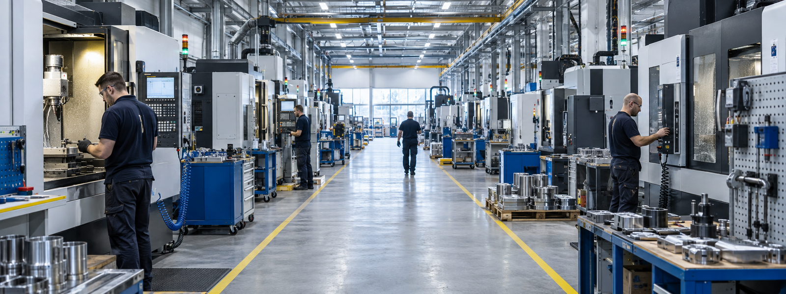
Key process variables include:
- Grinding wheel dressing: Frequent dressing maintains wheel sharpness and geometry, reducing grinding forces and heat generation. Over-dressing accelerates wheel consumption; under-dressing causes workpiece burning and dimensional drift.
- Regulating wheel speed: Controls workpiece rotation and feed rate. Incorrect speed ratios produce chatter, spiral marks, or inconsistent diameter.
- Work blade height and angle: The blade supports the workpiece and defines the centerline height relative to the wheel axes. Small deviations introduce taper or out-of-roundness.
- Coolant flow and filtration: Adequate coolant flow removes grinding swarf and dissipates heat. Contaminated coolant or insufficient flow causes thermal expansion and surface defects.
- Stock removal strategy: Roughing passes remove bulk material quickly, while finishing passes with reduced depth of cut and slower feed rates achieve final dimensions and surface finish.
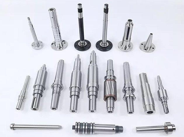
For applications requiring tight bore and shaft fit tolerances, such as precision shaft assemblies, centerless grinding is often paired with post-process inspection using air gauging or laser micrometers to confirm dimensional consistency within the specified tolerance band.
Inspection Methods and Acceptance Criteria for Ground Components
Validating centerless grinding tolerances requires measurement tools capable of resolving dimensional variation at the sub-micron level. Visual inspection and manual micrometers are insufficient for parts specified to ±0.0002″ or tighter. Instead, production environments rely on automated air gauging, laser scanning micrometers, or coordinate measuring machines (CMMs) to collect statistically meaningful data across each batch.
Air gauging measures diameter by detecting changes in air pressure as the part passes through a precision nozzle. This method provides real-time feedback and can be integrated into the grinding cell for closed-loop process control. Laser micrometers offer non-contact measurement and are well-suited for delicate or thermally sensitive components.
Roundness is typically assessed using a spindle-based roundness tester that rotates the part while a stylus traces the circumference. The resulting polar plot reveals lobing, ovality, or high-frequency chatter marks that indicate process instability. For parts with tight concentricity requirements, such as multi-diameter shafts, CMM inspection with multiple diameter measurements along the length is necessary to verify form and position tolerances.
Surface finish is measured using a profilometer, which quantifies arithmetic average roughness (Ra) and peak-to-valley height (Rz). These parameters affect wear resistance, sealing performance, and fatigue strength in high-stress applications.
Statistical Sampling and Batch Acceptance
For high-volume production, 100% inspection is often impractical. Instead, statistical process control (SPC) methods define sampling frequencies and acceptance limits based on process capability indices (Cpk). A Cpk value above 1.33 indicates that the process consistently produces parts within the tolerance band with minimal risk of defects. Lower Cpk values suggest insufficient process stability and require corrective action before continuing production.
Buyer’s Checklist: Evaluating a Centerless Grinding Supplier
When sourcing centerless ground components, procurement teams should verify that the supplier has the process capability, inspection infrastructure, and quality systems to deliver parts within the specified tolerance band. Use this checklist during supplier qualification:
- Request process capability studies (Cpk data) for similar parts and materials.
- Confirm availability of in-process gauging (air gauging, laser micrometers) for real-time dimensional feedback.
- Verify coolant filtration and thermal management systems to prevent dimensional drift during long production runs.
- Review wheel dressing protocols and frequency to ensure consistent surface finish and geometry.
- Ask for roundness and surface finish data from recent production batches, not just nominal tolerances.
- Ensure the supplier can provide first article inspection reports (FAIR) with full dimensional and geometric verification.
- Confirm traceability systems for batch control, especially for aerospace or medical applications requiring lot-level documentation.
For complex assemblies involving multiple precision-ground components, coordinate with suppliers early in the design phase to ensure that specified tolerances are achievable without excessive cost or lead time. If your project involves high-volume production with tight geometric requirements, consider requesting a detailed capability review before finalizing the specification.
Frequently Asked Questions
What is the tightest diameter tolerance achievable with centerless grinding?
Under optimal conditions with hardened materials, rigid geometry, and closed-loop process control, centerless grinding can achieve diameter tolerances as tight as ±0.0001″. However, this requires specialized equipment, frequent wheel dressing, in-process gauging, and rigorous thermal management. For most production applications, ±0.0002″ to ±0.0003″ represents a practical and cost-effective tolerance band that balances precision with throughput.
How does centerless grinding roundness compare to cylindrical grinding?
Centerless grinding typically produces roundness values between 0.0001″ and 0.0003″, which is comparable to or slightly better than conventional cylindrical grinding for rigid, short-length parts. The self-centering action of the process naturally corrects minor out-of-roundness with each workpiece rotation. However, for parts with high L/D ratios or interrupted surfaces, cylindrical grinding with tailstock support may deliver better geometric control.
Can centerless grinding handle interrupted surfaces or parts with keyways?
Centerless grinding is best suited for continuous cylindrical surfaces. Parts with keyways, flats, or holes cause the grinding wheel to intermittently lose contact, introducing vibration and dimensional variation. While some machines can accommodate interrupted surfaces with modified wheel geometries or specialized fixturing, these features often require secondary operations such as surface grinding or wire EDM to meet tight tolerances.
What surface finish range is typical for centerless grinding?
Surface finish depends on wheel grit size, feed rate, and material hardness. Roughing operations with coarse wheels (46–60 grit) typically produce Ra values of 32–63 µin, while finishing passes with fine wheels (120–220 grit) achieve Ra values of 8–16 µin on hardened steels. Ultra-fine finishes below 4 µin are possible with superfinishing wheels and reduced feed rates, though this increases cycle time and cost.
How does material hardness affect centerless grinding tolerances?
Harder materials such as tool steels, carbides, and ceramics grind to tighter tolerances because they resist deflection under grinding forces and maintain dimensional stability during thermal cycling. Softer materials like aluminum or annealed stainless steel may deflect during grinding or expand unpredictably due to lower thermal conductivity, widening the achievable tolerance band. Pre-hardening or stress-relief heat treatment improves tolerance consistency for materials prone to distortion.
What inspection equipment is required to verify sub-thousandth tolerances?
Verifying tolerances below ±0.001″ requires precision measurement tools such as air gauges, laser scanning micrometers, or coordinate measuring machines (CMMs) with resolution of at least 0.00005″. Manual micrometers and calipers lack the repeatability and resolution needed for this level of precision. For roundness verification, a spindle-based roundness tester with stylus resolution below 0.00001″ is necessary to detect lobing or chatter marks that affect assembly performance.
Conclusion
Centerless grinding tolerances are not arbitrary specifications—they are the result of controlled interaction between workpiece geometry, material properties, wheel selection, and process discipline. Engineering teams that understand these relationships can design components with realistic tolerance bands, select capable suppliers, and implement inspection protocols that validate dimensional consistency across production volumes. Whether your application involves high-volume automotive shafts, precision medical guidewires, or hardened aerospace pins, the key to reliable outcomes lies in aligning design intent with proven process capability and verifiable inspection evidence.
Sources
- WSM Technology, “Centerless Grinding: The Science of Precision,” https://www.wsmtechnology.com/feeds/blog/precision-centerless-grinding
- Ripley Machine, “Centerless Grinding: A Complete Guide,” https://www.ripley-machine.com/blog-and-news/centerless-grinding-a-complete-guide
- Centerless Grinders, “CNC Centerless Grinding: Complete Guide to Precision,” https://centerlessgrinders.com/cnc-centerless-grinding-the-complete-guide-to-precision-and-efficiency/